
Visualization device and method for visualizing particle deposition process in filter.

A sedimentation process and filter technology, which is applied in the field of visualization devices for the particle deposition process inside the filter, can solve the problems that it is difficult to truly reflect the deposition distribution law, and achieve the effects of convenient experimental observation, portability, and convenient disassembly

Active Publication Date: 2019-12-13
HUAZHONG UNIV OF SCI & TECH
View PDF11 Cites 0 Cited by
  • Summary
  • Abstract
  • Description
  • Claims
  • Application Information

AI Technical Summary

Problems solved by technology

The above-mentioned device for soot particle filtration experiments based on a single-sided or three-sided structure is quite different from the actual four-sided flow filtration structure in the DPF hole, so the experimental results are difficult to truly reflect the four-sided filtration of soot particles in the actual DPF elongated pores The regularity of deposition distribution

Method used


Image

  • Visualization device and method for visualizing particle deposition process in filter.
  • Visualization device and method for visualizing particle deposition process in filter.
  • Visualization device and method for visualizing particle deposition process in filter.

Examples


Embodiment 1

[0037] Taking a square filter channel in a particulate filter (DPF) as the research object, an observation device for simulating the visualization of DPF single channel and double-sided filtration is designed:

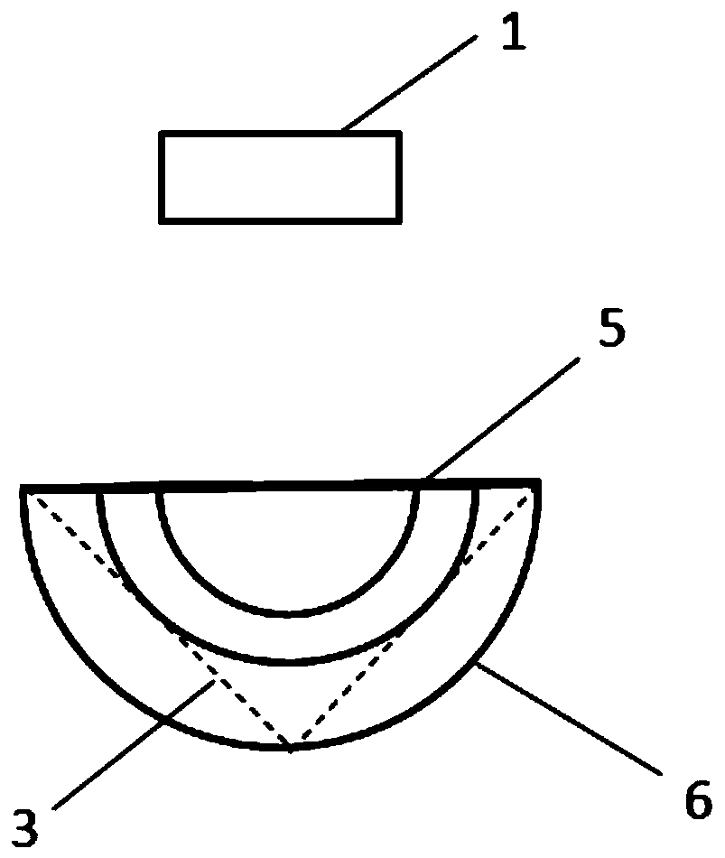
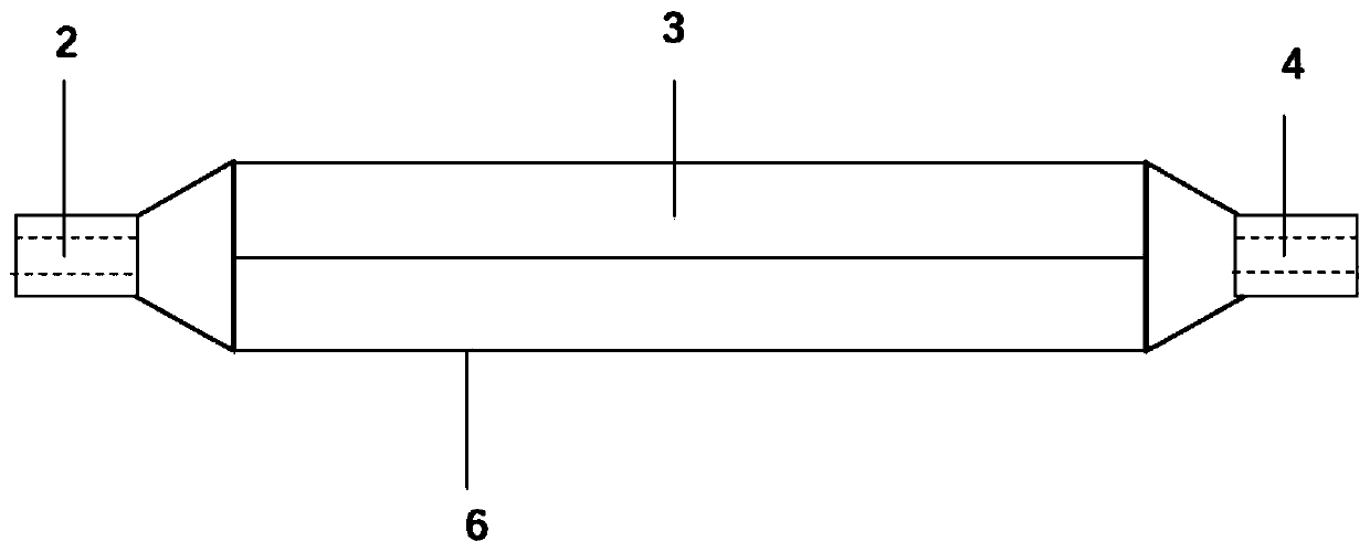
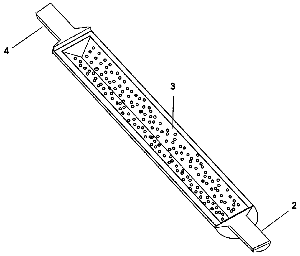
[0038] like Figure 1 to Figure 3 As shown, the actual filter channel cross-section is a square, its side length d=1mm, the designed filter channel 3 cross-section is an isosceles right triangle, the right angle side length is 10mm, and the filter channel 3 length is 100mm; filter inlet 2 and filter outlet 4 are all semicircular in section, with a diameter of 10mm; the transparent cover plate 5 is made of transparent glass, with a width of 20mm and a length of 100mm; the filter surface is filter paper, and the filter inlet 2, shell 6, filter outlet 4 and filter support surface Aluminum alloy is made by 3D printing.

[0039] When observing, the gas flow rate is controlled to be 1 / 10 of the gas flow rate in the actual filter, so that the Reynolds number is similar, that...


PUM


Abstract

The invention belongs to the field of particle deposition and filtration, and particularly discloses a visualization device and method for visualizing a particle deposition process in a filter. The visualization device comprise a filter inlet, a shell, a filter outlet, a filter pore canal and a transparent cover plate, wherein the filter inlet, the shell and the filter outlet are sequentially connected; the shape of the cross section of the filter pore canal is the same as the shape of a half of the cross section of an actual filter pore canal in the filter to be tested; the filter pore canalis positioned in the shell, wherein one end of the filter pore canal communicates with the filter inlet, the shell does not communicate with the filter inlet at the one end, the other end of the filter pore canal does not communicates with the filter outlet, and the shell communicates with the filter outlet at the other end; and the transparent cover plate covers the shell. The device can accurately simulate a filtering process in the actual pore canal, and can be used to observe the particle deposition filtering process along the axial section of the pore canal structure, so that the problemsthat the filtering pore canal in an actual filter is narrow and closed, and direct observation is difficult can be solved.

Description

technical field [0001] The invention belongs to the field of particle deposition filtration, and more specifically relates to a visualization device and method for particle deposition process inside a filter. Background technique [0002] Porous media is a common space occupied by multiphase substances, and it is also a combination of multiphase substances. The part of the space without a solid skeleton is called pores, which are shared by liquid or gas or gas-liquid two phases. In terms of phase, other phases are dispersed in it, and the solid phase is used as the solid skeleton, and some cavities that constitute the void space are connected to each other. In practical applications, porous media are often used to filter particulate matter in gases or liquids. [0003] The Diesel Particulate Filter (DPF) in practical application has been widely used due to its extremely high collection efficiency, but the deposition of soot particles in use will cause blockage in the filter...

Claims


Application Information

Patent Timeline
IPC IPC(8): B01D36/04B01D35/30G01N15/08
CPCB01D35/30B01D36/04G01N15/08G01N2015/084
Inventor 吴辉成晓北潘杰王东旭巴贤友
Owner HUAZHONG UNIV OF SCI & TECH
Learn More