
Profile drilling machine convenient for drill rod switching

A drilling machine and profile technology, which is applied in the direction of drilling/drilling equipment, boring machine/drilling machine parts, metal processing machinery parts, etc., can solve the problems of inconvenient use, achieve simple and fast operation, prevent safety accidents, and ensure interception effect of effect

Active Publication Date: 2019-12-13
SUZHOU WABOTE INTELLIGENT TECH CO LTD
View PDF7 Cites 3 Cited by
  • Summary
  • Abstract
  • Description
  • Claims
  • Application Information

AI Technical Summary

Problems solved by technology

At present, when the drilling equipment is replacing the drill pipe, it is necessary to repeatedly disassemble and assemble the drill pipe, which is inconvenient to use.

Method used


Image

  • Profile drilling machine convenient for drill rod switching
  • Profile drilling machine convenient for drill rod switching
  • Profile drilling machine convenient for drill rod switching

Examples


Embodiment 1

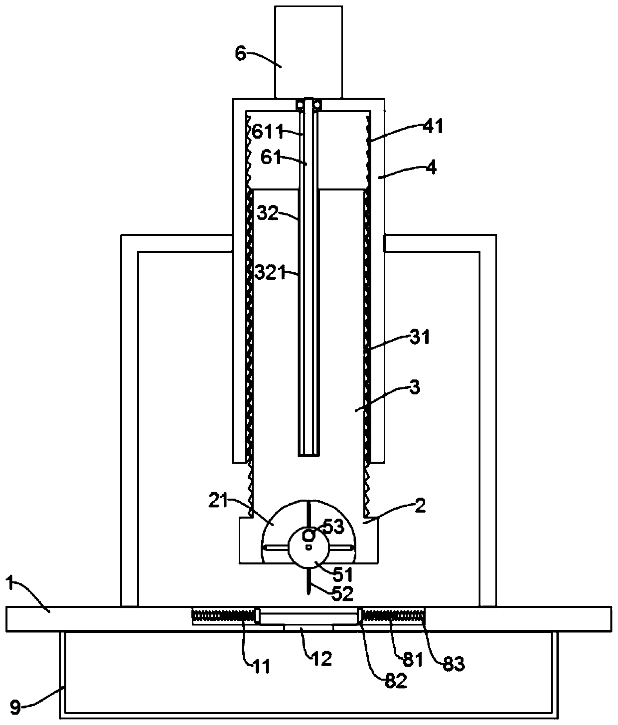
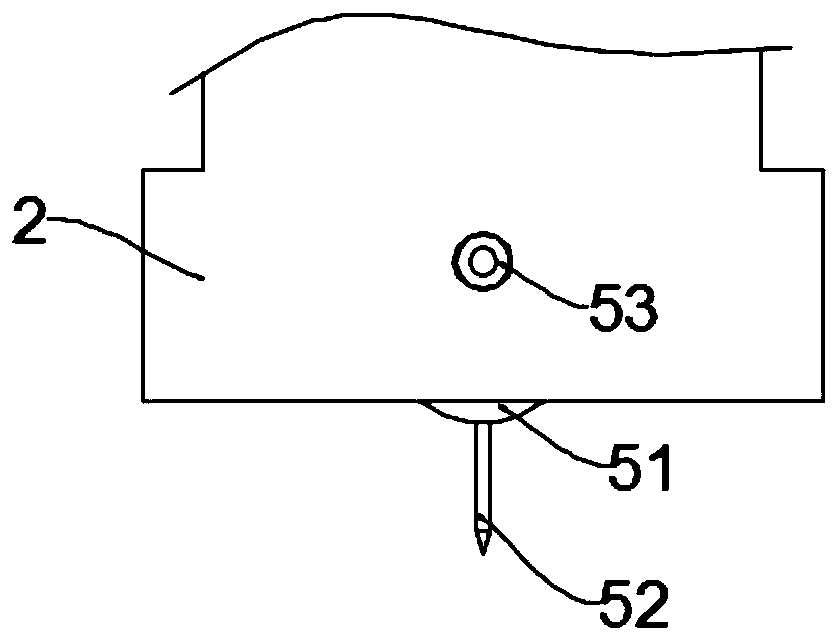
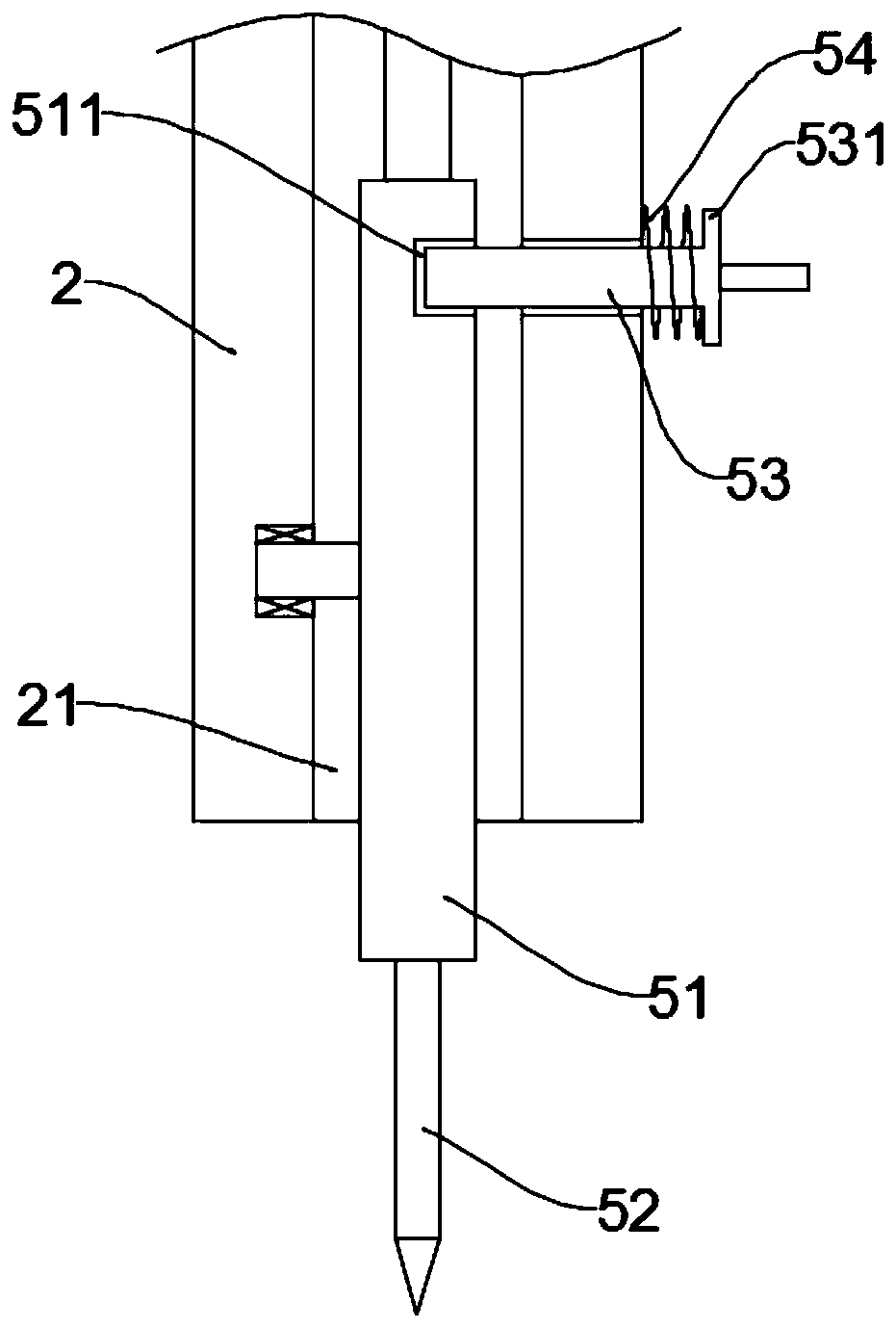
[0024] see Figure 1~4 , in an embodiment of the present invention, a profile drilling machine that is convenient for switching drill rods, includes a workbench 1, a storage slot 11 is provided on the worktable 1, and a drilling assembly is arranged above the storage slot 11; the drilling assembly It includes a base 2, which is driven by a screw-in drive assembly; the base 2 is provided with a cavity 21, and a turntable 51 is installed in the cavity 21, and a positioning mechanism for limiting the rotation of the turntable 51 is arranged on the base 2 , that is, the positioning mechanism can be used to fix the turntable 51 to limit its rotation; part of the turntable 51 protrudes from the cavity 21, and a plurality of drills with different diameters are equidistantly fixed on the circumferential surface of the turntable 51 along the circumferential direction. Rod 52, so that when in use, it can be rotated by turning the dial 51, so that the drill pipe 52 to be used is located ...

Embodiment 2

[0032] see Figure 5 , the embodiment of the present invention is expanded on the basis of embodiment 1, specifically:

[0033] Part of the waste slag will splash outward during the profile drilling process, which is likely to cause safety accidents. In order to avoid this situation, in this embodiment, the periphery of the base 2 is provided with a protective cover, and the protective cover is connected to the base through the connecting rod. 2 connection, so that it can be raised and lowered together with the base 2, so that the splashed waste residue can be effectively intercepted during the drilling process.

[0034] Further, the protective cover includes an upper cover body 71 and a lower cover body 72, the upper part of the lower cover body 72 is slidably inserted in the lower part of the upper cover body 71 and connected with the upper cover body 71 through a connecting spring 73, so that it can ensure The tight fit between the protective cover and the workbench 1 ensu...


PUM


Abstract

The invention discloses a profile drilling machine convenient for drill rod switching, and relates to drilling equipment. The drilling machine comprises a worktable; an object placing tank is formed in the worktable; a drilling module is arranged above the object placing tank, and comprises a base driven through a screwing driving module; a cavity is formed in the base; a rotating disc is rotationally mounted in the cavity; the base is provided with a positioning mechanism for limiting rotation of the rotating disc; part of a disc body of the rotating disc extends out of the cavity; and multiple drill rods with different rod diameters are fixed on the peripheral surface of the rotating disc in the peripheral direction at equal intervals. Through arrangement of the drilling module consisting of the base and the rotating disc, and through arrangement of a positioning mechanism, the switching of the drill rods can be realized through poking of the rotating disc without repeated disassembly, so that the switching efficiency is improved.

Description

technical field [0001] The invention relates to a drilling device, in particular to a profile drilling machine which is convenient for switching drill rods. Background technique [0002] As the name implies, a drilling machine is a device used to drill holes in objects, and it is also a device often used in profile processing. [0003] According to different process requirements, holes with different apertures need to be drilled during profile processing, which requires the use of various drill pipes. At present, when the drilling equipment is replacing the drill pipe, it is necessary to repeatedly disassemble and assemble the drill pipe, which is inconvenient to use. Contents of the invention [0004] The object of the present invention is to provide a profile drilling machine which is convenient for switching drill rods, so as to solve the above problems. [0005] To achieve the above object, the present invention provides the following technical solutions: [0006] A...

Claims


Application Information

Patent Timeline
Patent Type & Authority Applications(China)
IPC IPC(8): B23B47/00B23Q3/157B23Q11/00B23Q11/08
CPCB23B47/00B23Q3/157B23Q11/0042B23Q11/08
Inventor 徐政
Owner SUZHOU WABOTE INTELLIGENT TECH CO LTD
Learn More