
Abrasive belt polishing machine

An abrasive belt polishing and rotating body technology, applied in abrasive belt grinders, grinding/polishing equipment, grinders, etc., can solve problems such as disassembly and assembly of rotary joints, inconvenient maintenance, etc., to ensure long-term stable operation, improve service life, Improve the effect of fever

Active Publication Date: 2019-12-13
ZHEJIANG JIULI HI TECH METALS
View PDF7 Cites 0 Cited by
  • Summary
  • Abstract
  • Description
  • Claims
  • Application Information

AI Technical Summary

Problems solved by technology

[0004] The purpose of the present invention is to provide an abrasive belt polishing machine to solve the problem of inconvenient disassembly and maintenance of the rotary joint

Method used


Image

  • Abrasive belt polishing machine
  • Abrasive belt polishing machine
  • Abrasive belt polishing machine

Examples


Embodiment

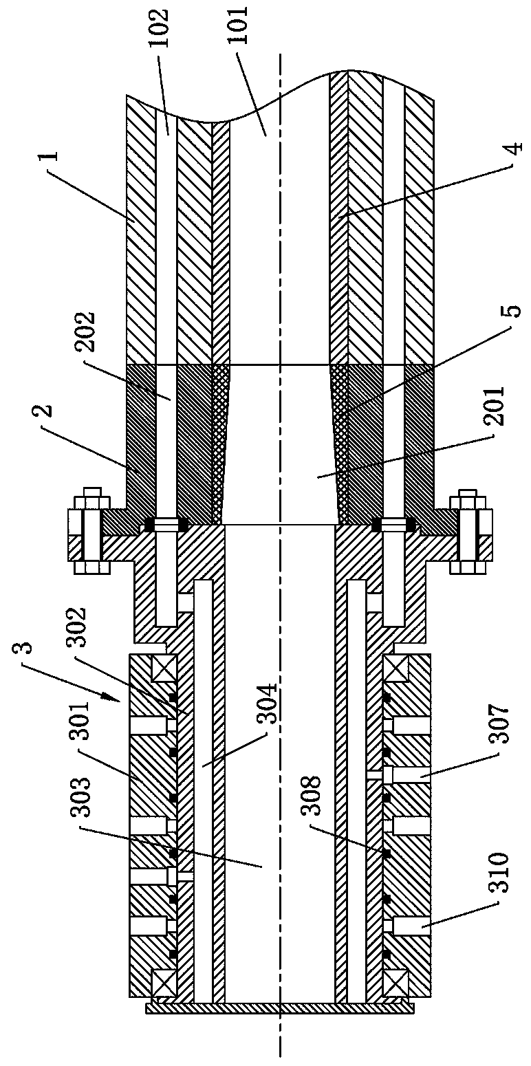
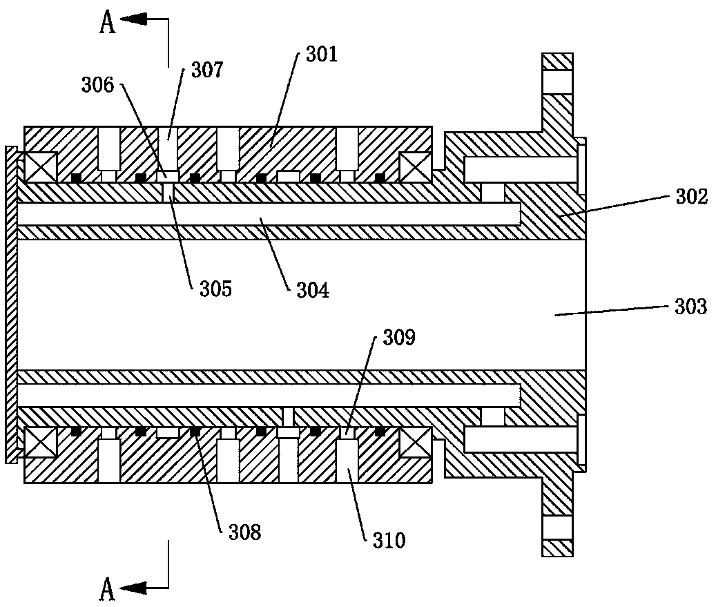
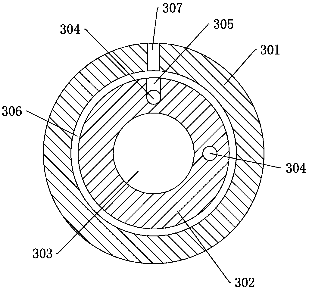
[0027] Example: such as figure 1 , figure 2 and image 3 As shown, an abrasive belt polishing machine includes a main shaft 1, a transition joint 2 and a rotary joint 3. The main shaft 1 is a hollow shaft, and the center of the main shaft 1 is provided with a first through hole 101 axially penetrating through it. The rotary joint 3 is located at the end of the main shaft 1, and the other end of the main shaft 1 is equipped with a large disc and a grinding head driven by an air cylinder. The main shaft 1 is horizontally installed on the frame through the bearing seat, and the rotary joint 3 is connected with a compressed air generator, such as a high-pressure air pump .

[0028] Such as figure 2 As shown, the rotary joint 3 includes a fixed body 301 and a rotating body 302. The fixed body 301 is sleeved on the outside of the rotating body 302, and is mounted on the rotating body 302 through a rotating shaft, and the two rotate relatively. The rotating body 302 is arranged...


PUM


Abstract

The invention relates to an abrasive belt polishing machine. The polishing machine comprises a main shaft and a rotary joint. First gas path channels are arranged in the main shaft. The rotary joint comprises a fixed body and a rotating body. High-pressure gas connecting holes are formed in the fixed body. The rotating body is arranged at the end of the main shaft and synchronously rotates with the main shaft, and the rotating body is internally provided with at least two second gas path channels. Each second gas path channel communicates with one corresponding first gas path channel. Groovesare formed in the fixed body, the high-pressure gas connecting holes communicate with the corresponding grooves respectively, vent holes are formed in the rotating body, and the second gas channels communicate with the corresponding grooves through the vent holes respectively. According to the polishing machine, the rotary joint is installed at the end of the main shaft, and disassembly, assemblyand later maintenance are facilitated. A ceramic wear-resistant layer is arranged on the outer wall of the rotating body, and a cooling structure is arranged between two sets of sealing structures sothat the phenomena of heating of the rotary joint and serious aging of sealing parts can be effectively relieved, and the service life of the rotary joint is further prolonged.

Description

technical field [0001] The invention relates to the technical field of polishing equipment, in particular to an abrasive belt polishing machine. Background technique [0002] Steel pipe surface polishing is one of the important links in the production of bright tubes. During the polishing process, the main shaft rotates with the large plate, and the rotary joint cannot rotate because it needs to be connected to the external compressed air pipeline, so there is a very large gap between the rotary joint and the main shaft. friction. After the rotary joint rubs against the main shaft, the rotary joint often has air leakage problems due to the easy damage of the sealing ring, resulting in a large amount of compressed air not being able to reach the cylinder on the large plate, causing the cylinder to not work or the pressure of the cylinder is not enough, affecting the surface polishing quality of the steel pipe. And it will cause damage to the spindle. [0003] Moreover, once...

Claims


Application Information

Patent Timeline
Patent Type & Authority Applications(China)
IPC IPC(8): B24B21/02B24B21/18
CPCB24B21/02B24B21/18
Inventor 华浩刘奎罗霞钟志宏王宝顺潘佳燕蔡志刚陈伟艾瑞驰·乌尔蒂希
Owner ZHEJIANG JIULI HI TECH METALS
Learn More