Backing-free top block for film laminating machine

A technology of laminating machine and top block, which is applied in synthetic resin layered products, lamination devices, lamination and other directions, can solve the problems of affecting work efficiency, insufficient application effect, waste of resources, etc., and achieves stable and reliable operation and application. Good effect, simple structure effect

Pending Publication Date: 2019-12-13
梁兴安
View PDF2 Cites 2 Cited by
  • Summary
  • Abstract
  • Description
  • Claims
  • Application Information

AI Technical Summary

Problems solved by technology

[0002] At present, when woodworking machinery and wood-based panels are laminated by ordinary laminating machines, the traditional way is to place the workpiece on the backing plate, requiring the size of the backing plate to be slightly smaller than the workpiece, so that a gap with a height difference is formed between the bottom surface of the workpiece and the working surface. Ensure that when the workpiece is covered with PVC film, the PVC film can cling to and cover the bottom surface of the workpiece over the bottom edge of the workpiece to ensure that the edge of the workpiece is smoothly in place. However, there are many types of workpieces and different sizes. Different sizes of backing plates are made for different workpieces, resulting in waste of resources, and frequent replacement of backing plates affects work efficiency
[0003] Therefore, people have developed the mode that replaces backing plate with automatic jacking block on work plate, the patent of publication number CN205380971U discloses the automatic jacking block of the working plate of three-dimensional vacuum laminating equipment for example, when this automatic jacking block moves, The central controller controls the work of the infrared emitter group and the infrared receiver group, and obtains the positions of the small pieces that are not completely covered by each workpiece in the feeding tray longitudinally row by row, so as to control the small pieces that are not completely covered by each workpiece row by row. The corresponding lever action directly below the block makes the top column hinged at the bottom of the support bar rotate counterclockwise around the pin axis, but this kind of top block needs scanning and positioning process, which has a high degree of automation. This kind of laminating machine is expensive, and for most For small and micro enterprises, the procurement cost is high
[0004] Most small and micro enterprises still use simple, practical, and low-cost ordinary laminating machines. For this reason, the patent with the publication number of CN109353107 A discloses a top block of the gravity automatic roof system applied to ordinary laminating machines. The block does not need the scanning positioning process, relying on the mutual cooperation of its own structure and gravity to realize the rotation of the pad block, but the structure of the top block is relatively complicated, the transmission operation is not flexible enough, and the actual application effect is not good enough

Method used


Image

  • Backing-free top block for film laminating machine
  • Backing-free top block for film laminating machine
  • Backing-free top block for film laminating machine

Examples


Embodiment Construction

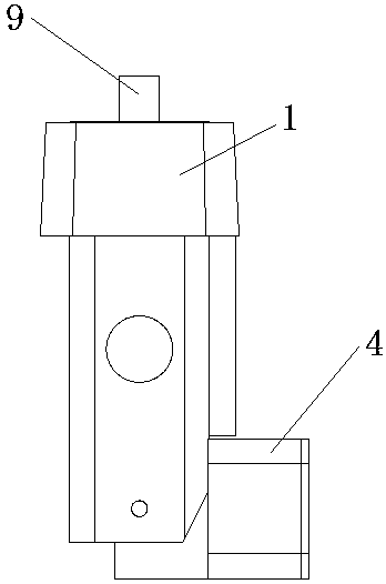
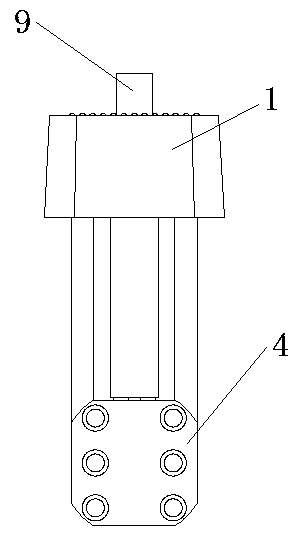
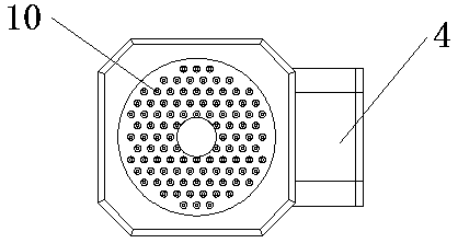
[0032] Such as Figure 1-5 As shown, the backing-free top block for the laminating machine includes a top block main body 1 and a spacer block 4, a rubber pad 10 is arranged in the center of the top of the top block main body 1, and a hole is opened in the middle of the rubber pad 10; Straight driving rack channel 11 and driven rack channel 12, a gear groove (not shown in the figure) is set between the driving rack channel 11 and driven rack channel 12, and the gear groove is located at the center hole of the rubber pad 10. Below, a gear 8 is arranged in the gear groove, and the gear 8 is installed on the top block main body 1 by the gear pin shaft 7. The driving rack 9 is arranged in the driving rack channel 11. The top of the driving rack 9 is bent, and the top of the driving rack 9 is bent. The folding section is located directly below the hole in the middle of the rubber pad 10, the lower part of the driving rack 9 meshes with the gear 8, and the spring 2 and the driven ra...


PUM


Abstract

The invention discloses a backing-free top block for a film laminating machine. The backing-free top block comprises a top block body and a cushion block, a driving rack channel and a driven rack channel are arranged in that main body of the top block, a gear is arranged between the driving rack channel and the driven rack channel, a driving rack is arranged in the driving rack channel, a lower part of the driving rack is meshed with the gear, a spring and a driven rack are arranged in the driven rack channel, the lower part of the driven rack is meshed with the gear, and a bulge is arranged at the lower end of the driven rack; a connection groove is arranged at that lower part of the top block main body, a cushion block is arranged at the lower part of the connection groove, the connection groove is rotatably connected with the cushion block, and a groove is arranged at the side part of the backing block. According to the invention, by ingeniously utilizing the gear to mesh with the driving rack and the driven rack on both sides respectively, when the gear rotates, the driving rack and the driven rack can move up and down in reverse direction, and under the pressure of the workpiece, the protrusion is separated from the groove, and the cushion block is released to rotate down; when the workpiece is removed, the bulge enters the groove to lock the cushion block. The invention has simple structure, adopts mechanical transmission mode, has flexible operation and stable and reliable action.

Description

technical field [0001] The invention belongs to the technical field of laminating machines, and in particular relates to a backing-free top block for laminating machines. Background technique [0002] At present, when woodworking machinery and wood-based panels are laminated by ordinary laminating machines, the traditional way is to place the workpiece on the backing plate, requiring the size of the backing plate to be slightly smaller than the workpiece, so that a gap with a height difference is formed between the bottom surface of the workpiece and the working surface. Ensure that when the workpiece is covered with PVC film, the PVC film can cling to and cover the bottom surface of the workpiece over the bottom edge of the workpiece to ensure that the edge of the workpiece is smoothly in place. However, there are many types of workpieces and different sizes. Backing plates of different sizes are made for different workpieces, resulting in waste of resources, and frequent r...

Claims


Application Information

Patent Timeline
Patent Type & Authority Applications(China)
IPC IPC(8): B32B37/10B32B27/30B32B27/06B32B21/08
CPCB32B37/10B32B21/08B32B27/304B32B27/06
Inventor 梁兴安
Owner 梁兴安
Why Eureka
Try Eureka