Synchronous lifting and moving type feeding equipment of engineering machinery

A technology of synchronous lifting and construction machinery, which is applied in the field of construction machinery, can solve the problem that construction personnel cannot know the material transportation situation in time, and achieve the effect of reducing material spillage and facilitating observation

Inactive Publication Date: 2019-12-13
徐州贝峰机械制造有限公司
View PDF8 Cites 0 Cited by
  • Summary
  • Abstract
  • Description
  • Claims
  • Application Information

AI Technical Summary

Problems solved by technology

[0002] With the development of social civilization and progress, colorful engineering projects are now completed and presented in front of the people. During the construction of engineering projects, the transportation of granular materials is an important part of engineering projects. The use of mechanized conveying equipment can not only improve the quality of engineering projects. The acceleration of the cycle can better guarantee the quality of the project construction. However, the existing technical feeding equipment adopts the fixed bracket type of use. After the feeding is completed, the construction personnel cannot know the material transportation situation in time, and manual labor is required when moving the equipment. For handling or dismantling, the conveying method inside the equipment is vertical rotation feeding, and some materials will accumulate inside the equipment after the construction is completed. There are many technical problems in the equipment under construction at this stage, and new technical equipment is needed to make up for it.

Method used


Image

  • Synchronous lifting and moving type feeding equipment of engineering machinery
  • Synchronous lifting and moving type feeding equipment of engineering machinery
  • Synchronous lifting and moving type feeding equipment of engineering machinery

Examples


Embodiment Construction

[0012] The present invention will be further described below in conjunction with the accompanying drawings.

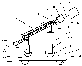
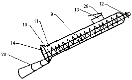
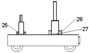
[0013] Such as Figure 1 to Figure 3 As shown, the present invention is a kind of synchronous liftable mobile feeding equipment for construction machinery, including a main body frame 1, a lifting system 2, a feeding device 3 and a kinetic energy system device 4, the upper part of the body frame 1 is connected to the lifting system 2, The upper part of the lifting system 2 is connected to the feeding device 3. The lifting system 2 is composed of a low lift 5 and a high lift 6. A low lift 5 is arranged on one side of the body frame 1 surface, and a high lift 6 is arranged on the other side of the body frame 1 surface. The feeding device 3 One end surface is welded with a fixed rod 7, the other end of the feeding device 3 is welded with a connecting rod 8, the top bolt of the low elevator 5 is connected with the fixed rod 7, the top bolt of the high elevator 6 is connect...


PUM


Abstract

The invention relates to synchronous lifting and moving type feeding equipment of engineering machinery. The synchronous lifting and moving type feeding equipment of the engineering machinery comprises a body frame, a lifting system, a feeding device and a kinetic energy system device, a low lift and a high lift are arranged on the two sides of the surface of the body frame, the top of the low lift is connected with the lower surface of the feeding device, the top of the high lift is connected with the upper surface of the feeding device, wherein the feeding device comprises feeding machine equipment, a feeding shell protection layer, a discharging detector and a bearing, the feeding machine equipment is arranged in the middle of the feeding device, the top end of a rolling shaft of the feeding machine equipment is provided with a flanged threaded flange, the upper surface of the feeding machine equipment is provided with a feeding port, the bottom of the feeding machine equipment is provided with a discharging port, the inner surface of the bottom of the feeding machine equipment is internally embedded with the discharging detector, the feeding machine equipment is connected witha speed reducer through the bearing, the speed reducer is connected with a motor through the rolling shaft, and rollers are arranged at the bottom of the body frame. According to the synchronous lifting and moving type feeding equipment, a lifting system is flexibly applied, and the use of the detector is effectively prepared for subsequent material conveying.

Description

technical field [0001] The invention relates to a synchronously lifting movable feeding device for engineering machinery, which belongs to the technical field of engineering machinery. Background technique [0002] With the development of social civilization and progress, colorful engineering projects are now completed and presented in front of the people. During the construction of engineering projects, the transportation of granular materials is an important part of engineering projects. The use of mechanized conveying equipment can not only improve the quality of engineering projects. The acceleration of the cycle can better guarantee the quality of the project construction. However, the existing technical feeding equipment adopts the fixed bracket type of use. After the feeding is completed, the construction personnel cannot know the material transportation situation in time, and manual labor is required when moving the equipment. For handling or dismantling, the conveyi...

Claims


Application Information

Patent Timeline
Patent Type & Authority Applications(China)
IPC IPC(8): B65G41/00B65G33/24
CPCB65G33/24B65G41/005B65G41/008
Inventor 张利
Owner 徐州贝峰机械制造有限公司
Why Eureka
Try Eureka