
Concave steel plate concrete composite wall

A steel plate concrete and composite wall technology, applied to walls, building components, buildings, etc., can solve the problems of high operational difficulty, increased production costs, waste of steel, etc., and achieve the effects of small steel consumption, reduced production costs, and reduced difficulty

Pending Publication Date: 2019-12-13
北京和筑科技有限公司
View PDF0 Cites 0 Cited by
  • Summary
  • Abstract
  • Description
  • Claims
  • Application Information

AI Technical Summary

Problems solved by technology

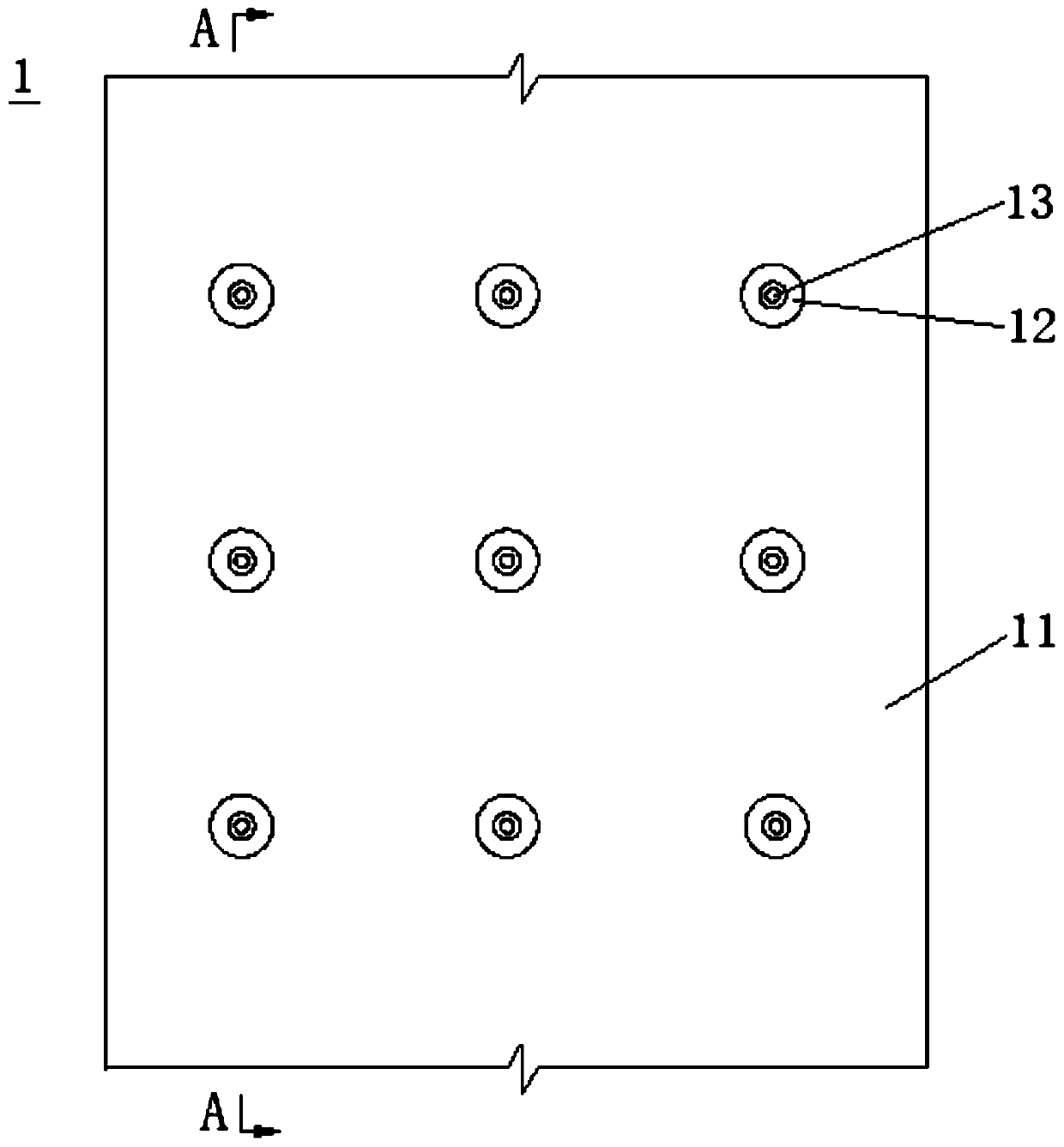
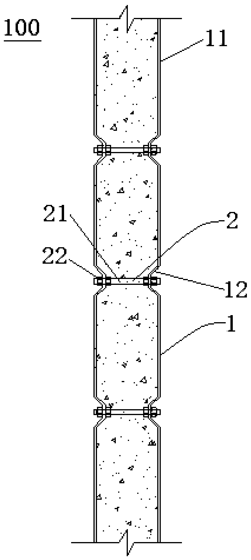
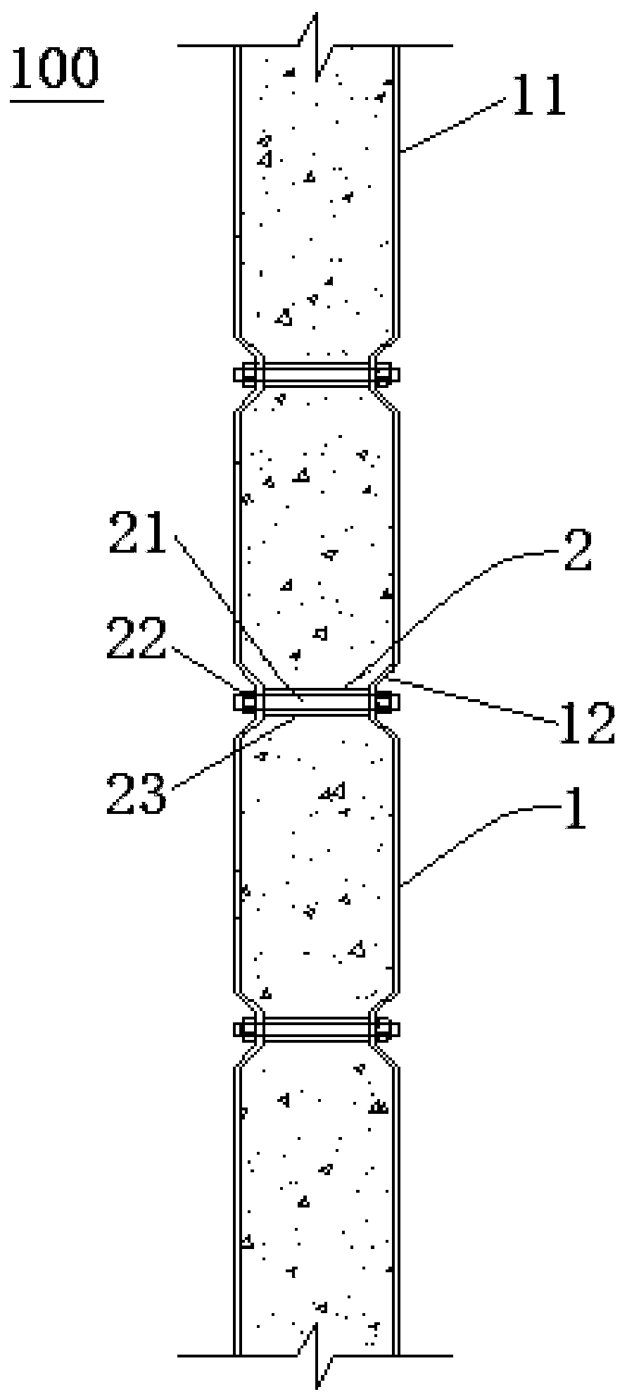
[0006] The purpose of this application is to provide a sunken steel plate concrete composite wall, which is used to solve the technical problems that the operation difficulty of forming a flat wall on the outside of the existing sunken steel steel concrete composite wall is relatively high, the production cost is increased, or steel is easy to be wasted

Method used


Image

  • Concave steel plate concrete composite wall
  • Concave steel plate concrete composite wall
  • Concave steel plate concrete composite wall

Examples


Embodiment Construction

[0043] Embodiments of the present invention are described in detail below, examples of which are shown in the drawings, wherein the same or similar reference numerals designate the same or similar elements or elements having the same or similar functions throughout. The embodiments described below by referring to the figures are exemplary only for explaining the present invention and should not be construed as limiting the present invention.

[0044] Those skilled in the art will understand that unless otherwise stated, the singular forms "a", "an", "said" and "the" used herein may also include plural forms. It should be further understood that the word "comprising" used in the description of the present invention refers to the presence of said features, integers, steps, operations, elements and / or components, but does not exclude the presence or addition of one or more other features, Integers, steps, operations, elements, components, and / or groups thereof. The expression "a...


PUM


Abstract

The invention provides a concave steel plate concrete composite wall, comprising a main wall unit; the main wall unit includes two steel plates and a plurality of connectors; and the two steel platesare relatively arranged, each steel plate includes a steel plate main body and a plurality of concave parts, the concave parts are arranged at the inner sides of the steel plate main bodies, and the bottom surfaces, far away from the steel plate main bodies, of the concave parts are provided with connecting holes; and the two end portions of each connector respectively penetrate through the two connecting holes corresponding to the two steel plates, and are fixedly connected with the two connecting holes respectively. Due to the fact that the concave parts are arranged at the inner sides of the steel plate main bodies, compared with a corrugated steel plate, the outer sides of the steel plate bodies of the concave steel plate concrete composite wall are more flat, at the same time, all ormost of the end portions of the connectors are contained in the concave parts, and operation difficulty of coating filler materials on the outer sides of the steel plate main bodies is lowered; and inaddition, compared with the corrugated steel plate in the same effective width, steel plate main body consumption is less than the corrugated steel plate consumption, steel plate use efficiency is improved, and the material cost is lowered.

Description

technical field [0001] The present application relates to the field of building structural components, in particular to a sunken steel plate concrete composite wall. Background technique [0002] Steel structures have many advantages in the field of construction, such as standardized design, factory production, and assembly construction. Vigorously developing prefabricated steel structure buildings has multiple effects such as developing new energy-saving and environmental protection industries, improving building safety levels, and promoting the resolution of excess capacity. Accelerating the increase in the proportion of prefabricated buildings in the new construction area and the development of prefabricated steel structure buildings urgently require technological innovation and the need to improve the level of architectural design and construction. [0003] At present, the concave steel plate concrete composite wall is a commonly used prefabricated steel structure in th...

Claims


Application Information

Patent Timeline
IPC IPC(8): E04B2/56E04B2/58E04B2/64
CPCE04B2/56E04B2/58E04B2/562E04B2/64
Inventor 崔清树张跃峰祝晨光刘培祥王如生陈东东张欣刘凯
Owner 北京和筑科技有限公司
Learn More