Device and method for cooling metal strips or sheets

A technology for metal strips and metal plates, applied in the direction of workpiece cooling devices, quenching devices, metal rolling, etc., can solve the problems of increasing the amount of cooling liquid applied, unfavorable, uneven temperature distribution, etc., to prevent the increase of back pressure Effect

Inactive Publication Date: 2019-12-13
SMS GRP GMBH
View PDF2 Cites 0 Cited by
  • Summary
  • Abstract
  • Description
  • Claims
  • Application Information

AI Technical Summary

Problems solved by technology

Thus, in the direction away from the inflow (more precisely, in the direction of the end side of the chilled beam shown on the left in the graphic region), the applied quantity of cooling liquid increases, which leads to an increase in the width B of the delivery section. The unfavorable uneven temperature distribution of

Method used


Image

  • Device and method for cooling metal strips or sheets
  • Device and method for cooling metal strips or sheets
  • Device and method for cooling metal strips or sheets

Examples


Embodiment Construction

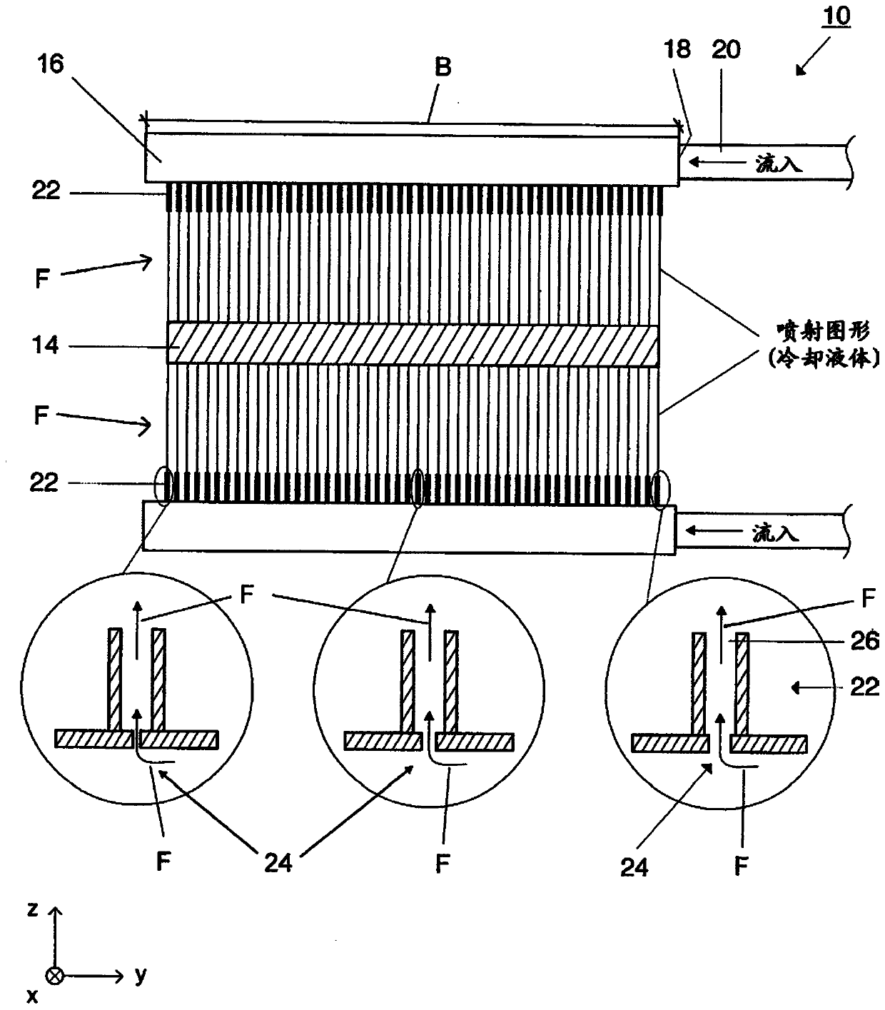
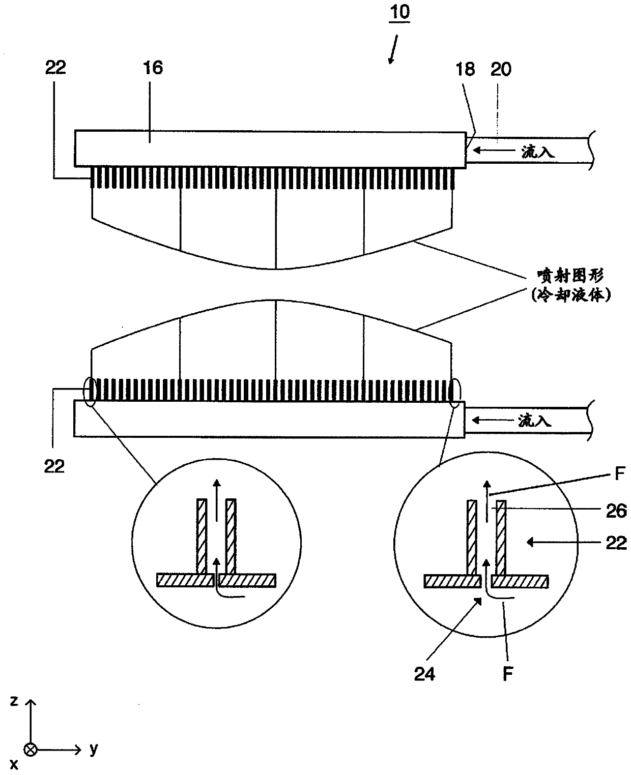
[0029] Refer below Figure 1 to Figure 3 A preferred embodiment of the device 10 according to the invention for cooling a metal strip and the corresponding method is explained. The device 10 is simplified in the figures and in particular is not shown to scale.

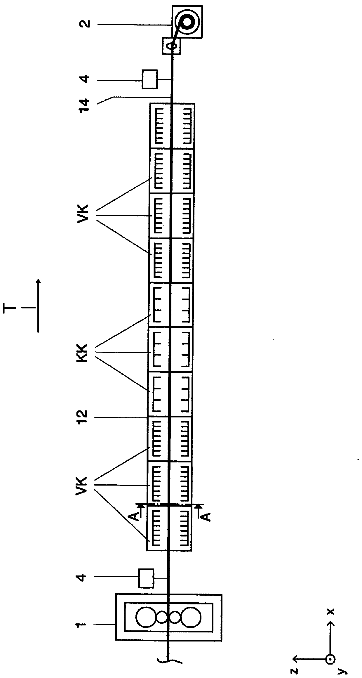
[0030] The device 10 serves to cool a metal strip 14 conveyed on a conveying section 12 . exist figure 2 The conveying section 12 is shown schematically in simplified form in a side view. Conveyor section 12 may be part of a finishing train whose last stand or rolling mill is at figure 2 Indicated by the reference numeral "1". The metal strip 14 is transported from the rolling mill 1 in the direction of the coiler 2, i.e. at figure 2 Transported from left to right in the illustration. A plurality of so-called intensive cooling groups VK are arranged along the conveying section 12 , ie with reference to the transport direction T of the metal strip 14 along the conveying section 12 (cf. figure 2 ) look at the ...


PUM


Abstract

The invention relates to a device (10) and a method for cooling metal strips or sheets conveyed on a conveyor section (12), in particular hot strips in the outlet of a rolling train. For this purpose,the device (10) comprises at least one cooling bar (16), which extends over the width (B) of the conveyor section (12), said cooling bar (16) having a connection point (18) to which a supply tube (20) for cooling liquid (F) can be connected, and a plurality of outlet openings (22) which are provided along a longitudinal axis of the cooling bar (16). Liquid (F) can be discharged in the direction of the metal strip or sheet (14) to be cooled through the outlet openings (22). The individual outlet openings (22) are paired with a respective adapted flow cross-section, wherein the flow cross-section of each outlet opening (22) decreases along the longitudinal axis of the cooling bar (16) in the direction away from the connection point (18).

Description

technical field [0001] The invention relates to a device for cooling metal strip or sheet metal conveyed on a conveying section according to the preambles of claims 1 and 4 and a corresponding method according to the preambles of claims 11 , 13 and 15 . Background technique [0002] When steel is manufactured, its mechanical properties can be influenced in several ways. Increased strength is achieved by addition of defined alloying elements (mixed crystal hardening). In addition, during rolling, the temperature of the finishing block can be lowered to achieve a higher dislocation density (dislocation hardening). By adding microalloying elements, such as Nb, V or Ti, precipitates are formed which lead to an increase in strength (precipitation hardening). However, the above-mentioned mechanism has the disadvantage that the toughness of the resulting material is thereby adversely affected. In contrast, the fine-grained structure of the structure (fine-grain hardening) favora...

Claims


Application Information

Patent Timeline
Patent Type & Authority Applications(China)
IPC IPC(8): C21D8/02C21D9/46C21D9/48C21D11/00C21D1/60C21D1/667B21B37/76B21B45/02
CPCB21B37/76B21B45/0218B21B45/0233C21D8/02C21D9/46C21D9/48C21D11/005C21D1/60C21D1/667B21B45/02C21D11/00
Inventor C·哈塞尔T·黑曼H-J·奥德欣肯H·贝格J·阿尔肯
Owner SMS GRP GMBH
Why Eureka
Try Eureka