
Injection compression molding process and equipment

A technology of compression molding and process, which is applied in the field of injection compression molding process and equipment, and can solve problems such as poor molding accuracy, decreased product repeatability, and reduced compression force.

Inactive Publication Date: 2019-12-17
何兆洪
View PDF5 Cites 0 Cited by
  • Summary
  • Abstract
  • Description
  • Claims
  • Application Information

AI Technical Summary

Problems solved by technology

[0003] First, use the direct injection molding technology of an injection molding machine that does not have the injection compression function, but the traditional direct injection molding technology makes the molten plastic generate a lot of stress in the mold cavity, and the transparent PC plastic mobile phone back cover and light guide plate produced are very easy. Deformation, unable to meet mobile phone assembly and optical requirements and appearance requirements
[0004] Second, the process of using a toggle-type all-electric injection molding machine with injection compression function for injection compression production process, using a toggle-type all-electric injection molding machine with injection compression function for injection compression production process, due to the toggle lock Due to the limitations of the mold mechanism, the compression force decreases sharply with the increase of the compression distance, and the compression distance cannot exceed 0.5mm. The process has great limitations and cannot meet the wide use of injection compression technology.
[0005] Third, the process of using a direct pressure injection molding machine with injection compression function for injection compression production, using a direct pressure injection molding machine with injection compression function for injection compression production process, due to the use of hydraulic clamping mechanism The position, that is, the position of the moving template before compression, has poor accuracy, and during the injection process, due to the formation of cavity pressure in the mold, it will cause the offset of the mold clamping position, which will lead to poor final molding accuracy and eventually affect the product. The repeat accuracy drops

Method used

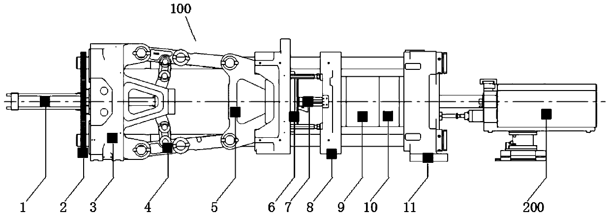
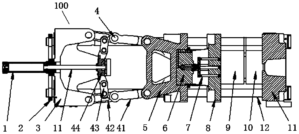
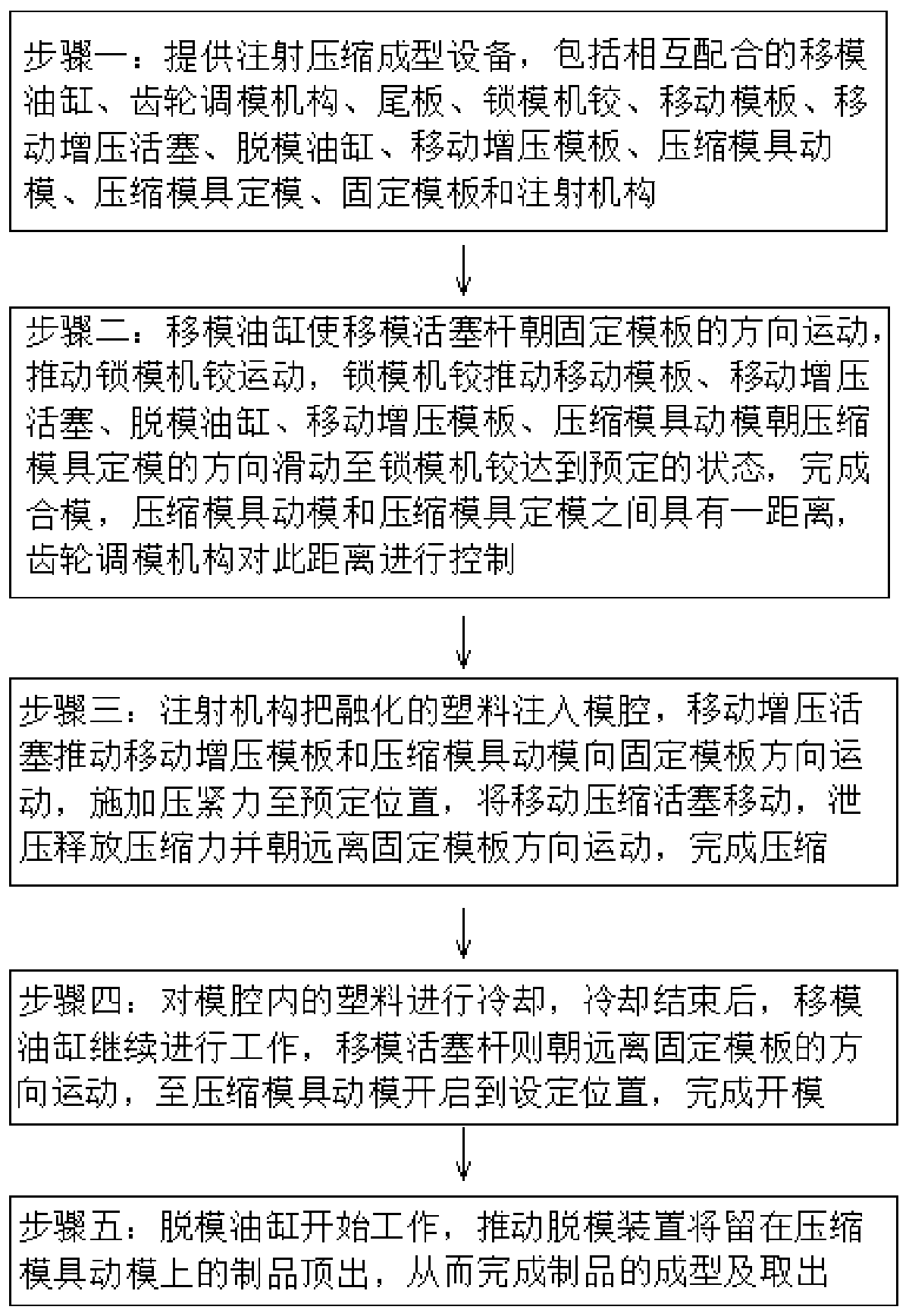

Image

  • Injection compression molding process and equipment
  • Injection compression molding process and equipment
  • Injection compression molding process and equipment

Examples


Embodiment Construction

[0032]In order to facilitate a better understanding of the purpose, structure, features, and effects of the present invention, the present invention will now be further described in conjunction with the accompanying drawings and specific embodiments.

[0033] See figure 1 and figure 2 , a kind of injection compression molding equipment 100, used for the injection mechanism 200 to inject melted plastic or glass liquid into products, the products can be mobile phone covers, light guide plates, car side glass and car sunroofs, etc., which include mold transfer pistons The mold-moving cylinder 1 of the rod 11, the mold-moving cylinder 1 and the gear mold-adjusting mechanism 2 are fixed on the tail plate 3, the clamping machine hinge 4 is connected with the mold-moving piston rod 11, and the mold-moving piston rod 11 pushes the mold-clamping machine hinge 4 Displacement toward the direction of the fixed template 11, the mobile booster piston 6 and the movable booster template 8 a...


PUM


Abstract

The invention discloses an injection compression molding process and equipment. According to the injection compression molding process and equipment, a mold moving oil cylinder makes a mold moving piston rod move, a mold locking machine hinge is pushed to move, the mold locking machine hinge pushes a moving mold plate, a moving pressurizing piston, a demolding oil cylinder, a moving pressurizing mold plate and a compression mold moving mold to slide until the mold locking machine hinge reaches a predetermined state to finish mold closing, a distance exists between the compression mold moving mold and a compression mold fixed mold, a mold cavity is formed between the compression mold moving mold and the compression mold fixed mold, an injection mechanism injects melted plastic into the moldcavity, the moving pressurizing piston pushes the moving pressurizing mold plate and the compression mold moving mold to move to the direction of a fixed mold plate, a compression force is applied tothe inner portion of the mold cavity, and then the melted plastic inside the mold cavity is compressed until to a predetermined position, then a moving compression piston is moved, pressure relief isperformed to release the compression force inside the mold cavity and moving away from the direction of the fixed mold plate is performed, a compression process is finished, product warping deformation is avoided, and the accuracy is guaranteed.

Description

【Technical field】 [0001] The invention relates to an injection compression molding process and equipment, in particular to an injection compression molding process and equipment with no warping and high precision. 【Background technique】 [0002] With the development of 5G communication, 3D plastic covers are more and more widely used in mobile phones and light guide plates. It is difficult for traditional injection molding process and equipment to fully meet product requirements. At present, there are three existing technologies for realizing 3D plastic mobile phone cover plates and light guide plates on the market: [0003] First, use the direct injection molding technology of an injection molding machine that does not have the injection compression function, but the traditional direct injection molding technology makes the molten plastic generate a lot of stress in the mold cavity, and the transparent PC plastic mobile phone back cover and light guide plate produced are v...

Claims


Application Information

Patent Timeline
IPC IPC(8): B29C45/56B29C45/68
CPCB29C45/561B29C45/681B29C2045/5635
Inventor 何兆洪邓伟新
Owner 何兆洪
Learn More