Fixed beam leaky-wave antenna with a customizable emergence angle

A technology of leaky wave antenna and fixed beam, applied in the field of fixed beam leaky wave antenna

Active Publication Date: 2019-12-17
SOUTHEAST UNIV
View PDF3 Cites 2 Cited by
  • Summary
  • Abstract
  • Description
  • Claims
  • Application Information

AI Technical Summary

Problems solved by technology

However, for fixed-beam application scenarios, such as point-to-point communication, large-bandwidth signal transmission, SAR radar, etc., the frequency sweep characteristic...

Method used


Image

  • Fixed beam leaky-wave antenna with a customizable emergence angle
  • Fixed beam leaky-wave antenna with a customizable emergence angle
  • Fixed beam leaky-wave antenna with a customizable emergence angle

Examples


Embodiment Construction

[0034] In order to make the purpose, technical solution and advantages of the present application clearer, the present application will be further described in detail below in conjunction with the accompanying drawings and embodiments. It should be understood that the specific embodiments described here are only used to explain the present application, and are not intended to limit the present application.

[0035] Reference herein to an "embodiment" means that a particular feature, structure, or characteristic described in connection with the embodiment can be included in at least one embodiment of the present application. The occurrences of this phrase in various places in the specification are not necessarily all referring to the same embodiment, nor are separate or alternative embodiments mutually exclusive of other embodiments. It is understood explicitly and implicitly by those skilled in the art that the embodiments described herein can be combined with other embodiment...


PUM


Abstract

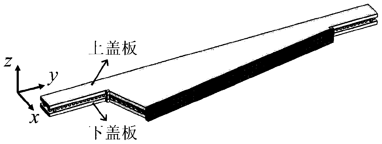
The invention discloses a fixed beam leaky-wave antenna with a customizable emergence angle. The antenna comprises a gap ridge waveguide uniform leaky-wave antenna (1), a triangular metal prism (2) and a transmission type phase gradient surface structure (3), wherein a leaky-wave surface of the gap ridge waveguide uniform leaky-wave antenna (1) is connected with an incident surface of the triangular metal prism (2), an emergent surface of the triangular metal prism (2) is connected with a row of transverse units in the middle of an incident surface of the transmission type phase gradient surface structure (3), the gap ridge waveguide uniform leaky-wave antenna (1) comprises a first metal plate, a second metal plate, a first metal ridge (11), a second metal ridge (12), a row of first periodic metal columns (13) connected with an upper metal plate and a lower metal plate, and a row of leaky-wave metal columns (14) with gradually changed heights, the triangular metal prism (2) comprises athird metal plate, a fourth metal plate, a second periodic metal column (21) and a third periodic metal column (22), wherein the third metal plate and the fourth metal plate are identical in size.

Description

technical field [0001] The invention relates to the technical field of novel antennas, in particular to a fixed-beam leaky-wave antenna with a customizable outgoing angle. Background technique [0002] As a new type of antenna, the leaky wave antenna has many characteristics that traditional resonant antennas do not have or are difficult to achieve, such as traveling wave mode, frequency sweep of radiation angle, high impedance bandwidth, high gain, and simple structure. In the past few decades, leaky-wave antennas have received extensive attention and research. The beam frequency scanning characteristic of the leaky wave antenna corresponds to the conversion of frequency domain-space domain signals, and can be applied to spectrum analysis, radar sensors, holographic imaging, etc. The periodic modulation leaky wave antenna and the leaky wave antenna based on the left and right hand transmission lines overcome the limitation that the traditional uniform traveling wave antenn...

Claims


Application Information

Patent Timeline
IPC IPC(8): H01Q13/20H01Q15/02H01Q19/06H01Q3/44
CPCH01Q3/44H01Q13/20H01Q15/02H01Q19/06
Inventor 程强陈建锋崔铁军
Owner SOUTHEAST UNIV
Why Eureka
Try Eureka