Grounding gun installed on rotating shaft

A grounding gun and shaft technology, applied in the field of grounding guns, can solve the problems of production reduction and load reduction, complex installation, high safety risks in online maintenance and replacement, and achieve the effect of improving product life and reducing costs.

Pending Publication Date: 2019-12-17
GUIZHOU JINCHI CHEM CO LTD
View PDF0 Cites 0 Cited by
  • Summary
  • Abstract
  • Description
  • Claims
  • Application Information

AI Technical Summary

Problems solved by technology

However, the existing grounding brushes have problems such as high cost, complicated installation, short service life, high safety risks for online maintenance and replacement, which in turn affect their normal operation, bury many hidden dangers for the equipment, and lead to production reduction and burden reduction.

Method used


Image

  • Grounding gun installed on rotating shaft
  • Grounding gun installed on rotating shaft
  • Grounding gun installed on rotating shaft

Examples


Embodiment Construction

[0038] Hereinafter, preferred embodiments of the present invention will be described in detail with reference to the accompanying drawings. It should be understood that the preferred embodiments are only for illustrating the present invention, but not for limiting the protection scope of the present invention.

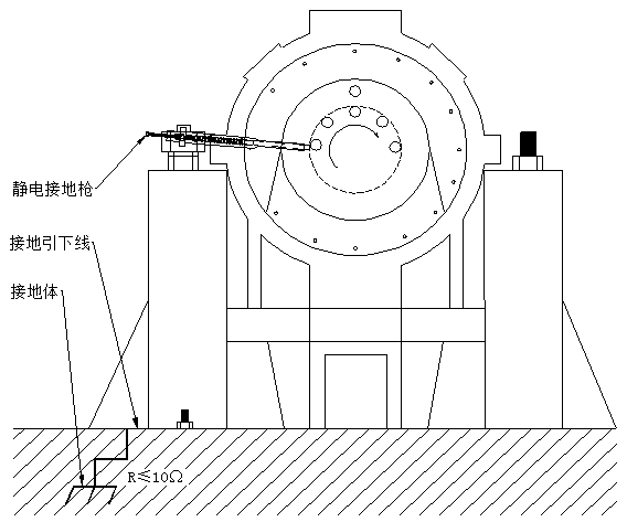
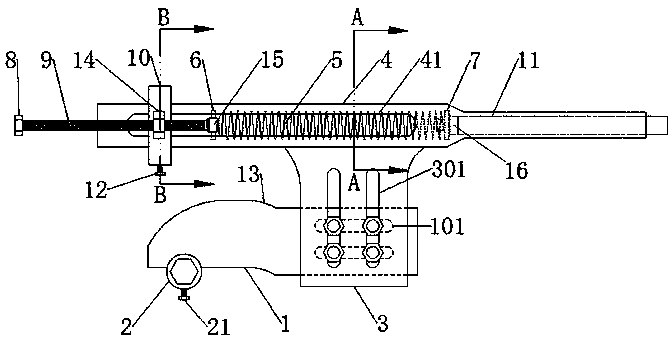
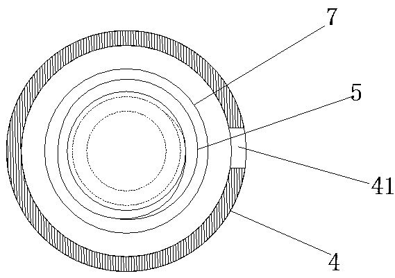
[0039] like Figure 1-6 As shown, a grounding gun installed on the rotating shaft, the grounding gun is connected to the steering support on the rotating shaft, conducts electricity through the graphite rod 11, and transmits the induced electricity to the steel pipe of the grounding gun through the second spring seat 7 4. Then it is transmitted to the second support plate 3 through the steel pipe 4 and then to the first support plate 1, and then transmitted to the second bolt 21 on the large cover of the unit through the fastening nut 2 on the first support plate 1, and then passed through the second The bolt 21 is transmitted to the compressor body, and finally relea...


PUM


Abstract

The invention discloses a grounding gun installed on a rotating shaft. The grounding gun is connected with a steering support on the rotating shaft and comprises a first supporting plate; a fasteningnut connected with a unit large cover bolt of the rotating shaft is connected below one end of the first supporting plate, and the other end is connected with a second supporting plate; the upper endof the second supporting plate is connected with a steel pipe; a through long-strip-shaped hole is axially formed in the middle of the pipe wall of the steel pipe; a spring is arranged in the steel pipe; a first spring seat and a second spring seat are respectively arranged at two ends of the spring; the other side of the second spring seat is connected with a graphite rod; an adjusting sleeve capable of axially sliding sleeves the outer wall of the steel pipe; a radial locking screw hole is formed in the adjusting sleeve; a locking bolt is connected to the radial locking screw hole, a positioning nut is connected to the radial side of the outer wall of the adjusting sleeve; a screw rod is arranged on the positioning nut; the end of the screw rod is connected with one end of a connecting rod; the other end of the connecting rod penetrates through the long-strip-shaped hole and then is connected with the first spring seat; and a rotating wheel facilitating rotation is arranged at the tail end of the screw rod.

Description

technical field [0001] The invention relates to a grounding gun installed on a rotating shaft, and belongs to the technical field of induction electric grounding equipment for rotating rotors. Background technique [0002] At present, some rotating mechanical equipment driven by steam will generate induced potential (voltage) on the rotating shaft when rotating due to its own mechanical or electrical characteristics. If the voltage relief system does not work properly or is not handled, the voltage will find an alternate path to ground, and the corresponding metal body will become a ground conductor for the induced voltage. Very typical is the bearing (bearing bush) or seal of the rotor, which is prone to arcing or electrostatic discharge. These arcs will damage the metal surface and increase the normal operation of the sealing gap between the components. If it is not handled in time, the bearing (bearing bush) and the seal will gradually be damaged, and the dynamic charact...

Claims


Application Information

Patent Timeline
Patent Type & Authority Applications(China)
IPC IPC(8): H05F3/02H01R39/415H01R39/26H01R39/20
CPCH01R39/20H01R39/26H01R39/415H05F3/02
Inventor 黄彬谢劲松王敏韩中喜潘勇陈志良况休生易昌国
Owner GUIZHOU JINCHI CHEM CO LTD
Why Eureka
Try Eureka