A waste lubricating oil coupling filter device
A technology of filtering device and lubricating oil, applied in the directions of lubricating composition, filtering separation, filtering circuit, etc., can solve the problems of filter screen blockage, affecting filtering efficiency, shortening downtime for screen replacement, etc., so as to increase the service life and reduce the difficulty of filtering. , the effect of increasing filtration efficiency and filtration quality
- Summary
- Abstract
- Description
- Claims
- Application Information
AI Technical Summary
Problems solved by technology
Method used
Image

Examples
specific Embodiment approach 1
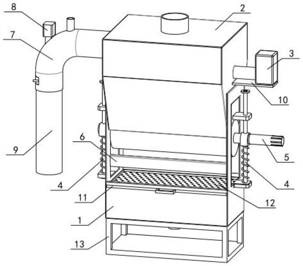
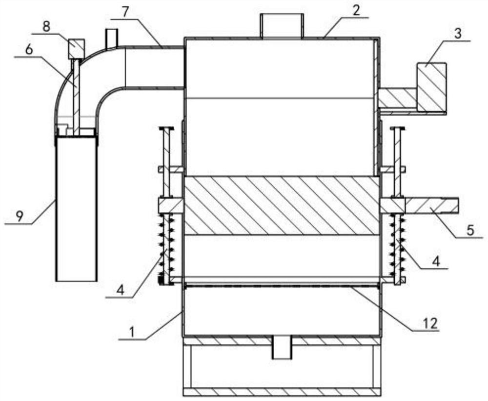
[0031] Such as Figure 1-11 As shown, a waste lubricating oil coupling filter device includes a recovery box 1, a pretreatment box 2, a booster 3, a booster rod 4, a pretreatment roller 5, a scraper 6, a sinking pipeline 7, a knocker 8, Processing pipe 9, motor seat 10, filter screen frame 11, filter screen II 12 and device base 13, the upper end of the recovery box 1 is fixedly connected to the pretreatment box 2, and the pretreatment box 2 is sealed and fixedly connected to the booster 3, pressurized There are two rods 4, the lower ends of the two booster rods 4 are slidingly connected with the recovery box 1, the upper ends of the two booster rods 4 are slidingly connected with the pretreatment box 2, and the pretreatment roller 5 is connected with the two booster rods. 4 Rotate connection, the pretreatment roller 5 is in sealing contact with the lower end of the pretreatment box 2, the scraper 6 is fixedly connected with the recovery box 1, the scraper 6 is located below t...
specific Embodiment approach 2
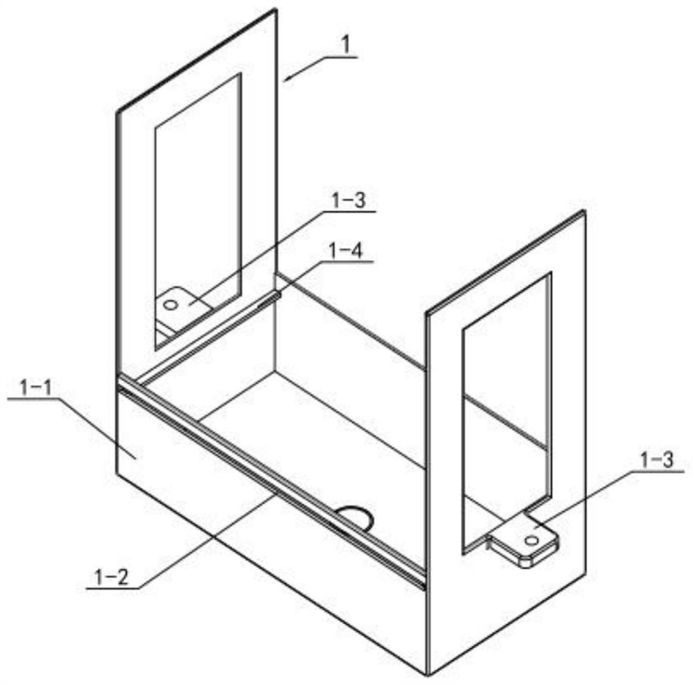
[0032] Such as Figure 1-11 As shown, the recovery box 1 includes a recovery box body 1-1, a sliding outlet 1-2, a limiting seat 1-3 and a support platform 1-4, and the upper side of the rear end of the recycling box body 1-1 is provided with a sliding outlet 1 -2, the left and right ends of the recovery box body 1-1 are respectively fixedly connected with a limiting seat 1-3, and the left and right sides of the inner end of the recovery box body 1-1 are respectively fixedly connected with a supporting platform 1-4; the filter screen frame 11 Slidingly connected on the two supporting platforms 1-4, the filter screen frame 11 is slidably connected in the sliding outlet 1-2, and the device base 13 is fixedly connected on the bottom surface of the recovery box body 1-1. The recovery box 1 is used to reclaim lubricating oil with large particles of impurities and metal particles produced during the operation of the pretreatment roller 5. The filter screen II 12 is installed on the ...
specific Embodiment approach 3
[0033] like Figure 1-11 As shown, the pretreatment box 2 includes a pretreatment box body 2-1, a limiting seat II 2-2, and an arc portion I2-3. The upper end of the pretreatment box body 2-1 is fixedly connected and communicated with a pipe. The left and right ends of the box body 2-1 are respectively fixedly connected to a limiting seat II 2-2, and the lower end of the pretreatment box body 2-1 is provided with an arc portion I2-3; the pretreatment box body 2-1 is fixedly connected to the recovery box body The upper end of the 1-1, the motor base 10 is fixedly connected to the right end of the pretreatment box body 2-1. The lower end of the pretreatment box body 2-1 should be gradually narrowed. The purpose is to make the impurities in the exhaust gas lubricating oil in the pretreatment box body 2-1 close to the cylinder electromagnet 5-1 when they are precipitated, so that the precipitated impurities are easy to approach. Cylindrical electromagnet 5-1, the pipe at the uppe...
PUM
 Abstract
Description
Claims
Application Information
 - R&D
- Intellectual Property
- Life Sciences
- Materials
- Tech Scout
- Unparalleled Data Quality
- Higher Quality Content
- 60% Fewer Hallucinations
Browse by: Latest US Patents, China's latest patents, Technical Efficacy Thesaurus, Application Domain, Technology Topic, Popular Technical Reports.
© 2025 PatSnap. All rights reserved.Legal|Privacy policy|Modern Slavery Act Transparency Statement|Sitemap|About US| Contact US: help@patsnap.com