[0003] (1) The
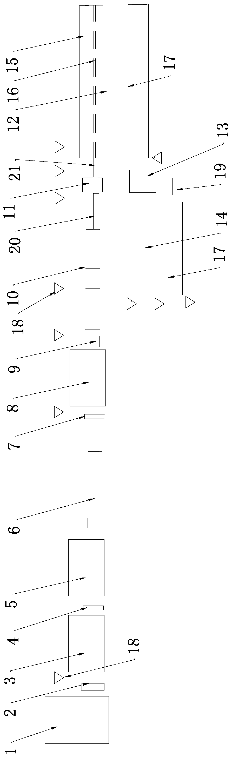
temperature monitoring on the production line cannot effectively supervise the temperature of the whole process of the rolled piece; (2) There is an unreasonable problem in the design structure of the original transition guide groove between the finishing rolling unit and the cooling device: the base of the guide groove adopts a fixed type , the guide groove is composed of four sections of about 55cm long seamless pipes placed on a bracket. The guide groove
branch pipe is made of seamless pipes welded on the guide entrance, fixed on the bracket with a pressure plate and an inclined iron, and the bracket is directly placed onto the fixed base
When a steel
pile accident occurs in the production of bars with this structure, the running bars are easy to
pile up and damage the equipment, resulting in serious deformation of the guide groove
branch pipe, and the continued use increases the probability of steel
pile accidents
In addition, the installation accuracy of the guide groove
branch pipe and the guide groove bracket is poor, and when it is used on the line, the front and rear centering of the outlet guide of the front finishing rolling unit and the inlet of the rear control cooling device are adjusted by adjusting the left and right positions of the guide groove bracket
Since the transition guide trough, the exit guide of the finishing
rolling mill, and the cooling device assembled on the traversing trolley are all moving, there is no fixed rolling center line reference point for comparison. This is a key point affecting production stability and a failure point for long-term stacking of steel
(3) The cooling device currently adopts a box-type water tank with a total length of 8.4m, which is installed on two traversing trolleys, which are connected by bolts, and the two trolleys are driven by separate hydraulic cylinders; After the
water pipe is passed through, the closing guide groove is also placed on the independent traversing trolley, which is driven by a separate
hydraulic cylinder, the trolley synchronization is poor, and the neutrality before and after passing through the water tank is poor
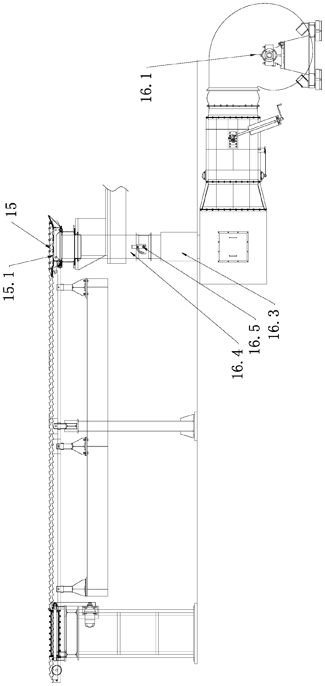
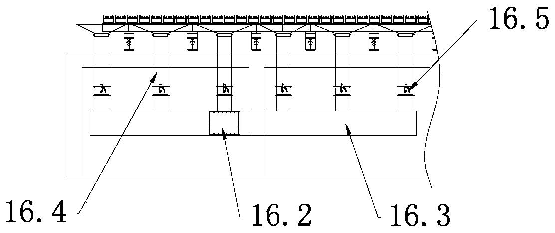
The
water pipe inside the water tank relies on circular pipe clamps to fix and align the water pipes. The circular pipe clamps are easy to
wear and tear, resulting in loose compression and seriously affecting the alignment.
There is no blowback air (or blowback water) device in the water-piercing device, and the water is seriously carried behind the
steel bar, resulting in uneven cooling on the surface of the
steel bar, which is prone to wavy bays and seriously affects the quality of the finished product
The
biggest problem is that the water-piercing device cannot realize single-line, single-group or intermittent
water transfer, and the single boiling water mode cannot meet the requirements for specifications and
process changes(4) The steel is placed on the cooling bed at 850-950°C, and no effective cooling measures are taken in the follow-up. The large-scale steel only relies on natural cooling to cool down, and the speed is slow. The subsequent
tempering temperature is high, and the grains of the structure will temper and grow. , the grain size of the steel becomes coarser, resulting in a decrease in performance
In addition, the straightening plate and the rack are easily deformed in the state of high temperature and
thermal expansion for a long time, resulting in bending deformation of the steel, and the
cooling speed of large specifications is too slow, resulting in bends or burrs during cold shearing, resulting in quality complaints
(5) When the steel is subjected to large cold shearing, the temperature is between 200°C and 450°C. Due to the high temperature, the head of the steel is prone to shear bends or burrs, which are caused by downstream customers during
welding or mechanical connection. Many problems, quality complaints also occur from time to time
(6) When the steel reaches the three-segment chain, the temperature is 200-400°C. This temperature range is just in the blue brittle range. The head of the steel turns blue, and the counter cannot work normally, which greatly increases the labor intensity of the workers.
(7) The temperature of the steel is around 200°C when it is collected and bundled. At this time, the steel is bundled and stored in a stack. The temperature of the stacked steel is high, the heat dissipation speed is slow, and it is in an aging state for a long time, resulting in a significant decline in the performance of the steel. To avoid qualified steel bars after aging, more alloys must be added, which increases production costs

