
Multi-wire slitting and rolling controlled cooling device for bar

A technology of split rolling and controlled cooling, which is applied in the direction of workpiece cooling devices, metal rolling, metal rolling, etc., and can solve the problem of poor alignment before and after passing through the water cooling device, uneven cooling of the bar surface, and increased risk of stacking steel and other problems to achieve rapid production process and production errors, avoid uneven cooling, and reduce the risk of stacking steel

Pending Publication Date: 2019-12-20
SHANDONG SHIHENG SPECIAL STEEL GROUP
View PDF0 Cites 1 Cited by
  • Summary
  • Abstract
  • Description
  • Claims
  • Application Information

AI Technical Summary

Problems solved by technology

Although the above-mentioned water-through cooling device can achieve a cooling effect, it has the following defects: First, the structure of two moving trolleys is used, which makes the front and rear alignment of the water-through cooling device poor, which may easily cause steel stacking accidents and affect the steel rolling production process; and the circular The pipe clamp is easy to loosen after frequent movement, and the water pipe under the high-pressure water supply is easy to shift, which affects the neutrality and increases the risk of stacking steel
Second, the cooling effect of the existing water-through cooling device is poor. During multi-line cooling, for the convenience of cooling, the cooling water of the multi-line bar is controlled by a unified switch, so that each line is supplied with water synchronously. However, in actual cooling, due to the rolling process Different, for example, there is an error of about 5-6 degrees Celsius in the rolled center line bar and side line bar. At the beginning of rolling, the error of manual neutral installation may cause a temperature difference of 15-20 degrees Celsius between the lines, which will cause Causes defects such as inconsistent quality of produced bars and high scrap rate
Third, when the existing water-cooling device cools the bar, the water is seriously carried along with the bar running, resulting in uneven cooling of the bar surface and wavy bending, which not only seriously affects the quality of the finished product, but also easily causes steel stacking accidents
Fourth, the cooling effect is relatively simple, which cannot meet the process requirements of segmental cooling according to different lengths
[0004] Among them, the existing transition guide groove adopts a fixed base structure, but the centering accuracy is poor due to the back and forth movement of the water tank, which is a long-term steel pile accident point

Method used


Image

  • Multi-wire slitting and rolling controlled cooling device for bar
  • Multi-wire slitting and rolling controlled cooling device for bar
  • Multi-wire slitting and rolling controlled cooling device for bar

Examples


Embodiment 1

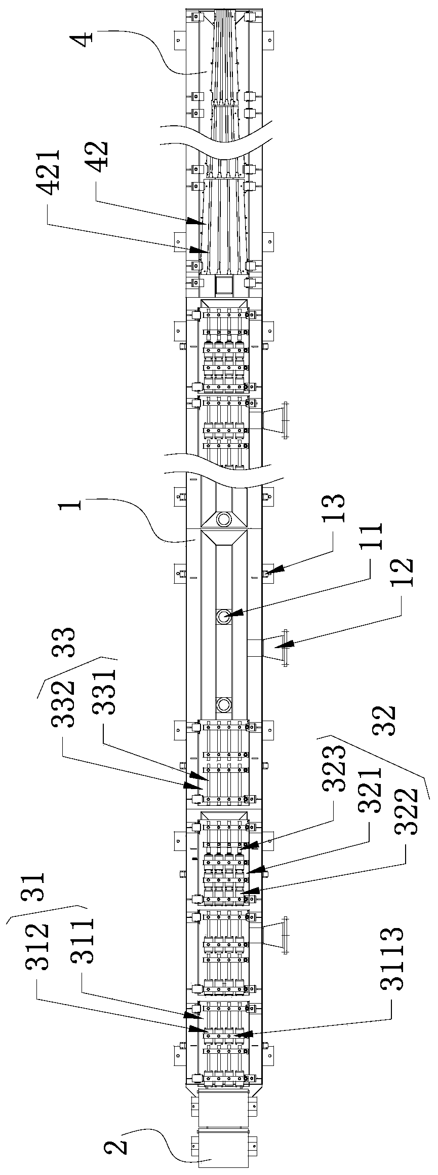
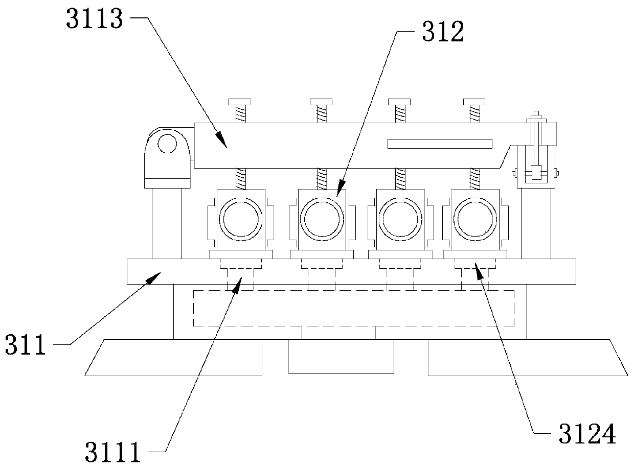
[0064] Such as Figure 1-10 As shown, in this embodiment, the multi-line slitting and rolling control cooling device of the bar includes a plurality of single-line cooling devices arranged in parallel, and the multiple single-line cooling devices are arranged on the same fixed water beam 1, so that the single-line cooling device can be improved. To be neutral and reduce the risk of bar stocking, each single-line cooling device includes a transition guide groove 2, a cooling structure 3, and a collection guide groove 4 arranged in sequence along the bar production direction. The cooling structure 3 includes a water cooling unit 31 and a counterattack Water unit 32 and empty unit 33;

[0065] The water cooling unit 31 includes a first assembly seat 311 installed on the fixed water beam 1, and a cooling nozzle 312 is installed on the first assembly seat 311. The cooling nozzle 312 is provided with a water inlet 3121 and a second assembly along the bar production direction. A chuckin...

Embodiment 2

[0080] Such as Picture 11 As shown, on the basis of Embodiment 1, the arrangement of the cooling structure is different from that of Embodiment 1. Specifically, the cooling structure consists of at least one water cooling unit—at least one counter-flushing water unit—at least one empty The minimum unit structure formed by the unit, and the cooling structure of adjacent single lines is the same. This arrangement can realize continuous cooling production of the bar. The water cooling unit 31 is used for cooling the bar through water, and the counter-water unit 32 is used to prevent the bar from backwards. Running with water, the empty passing unit 33 is used to guide the bar to the collecting guide groove.

Embodiment 3

[0082] Such as Picture 12 As shown, on the basis of Embodiment 1 or Embodiment 2, at least one empty passing unit 33 is provided at the beginning of the cooling structure, and the cooling structures 3 of adjacent single wires are the same. At this time, the empty passing unit 33 is used for guiding the bar from the transition channel to the water cooling unit 31, and can prevent the water of the water cooling unit 31 from being sprayed back to the temperature measuring device at the end of the transition channel to a certain extent, affecting its use.


PUM


Abstract

The invention relates to a multi-wire slitting and rolling controlled cooling device for a bar . The multi-wire slitting and rolling controlled cooling device for the bar comprises a plurality of single-wire cooling devices which are arranged in parallel; the multiple single-wire cooling devices are arranged on a same fixed water beam; the accuracy of alignment of a running middle line of the baris remarkably improved; the steel stacking risk of the bar is reduced; each single-wire cooling device comprises a transition guide groove, a cooling structure and a collection guide groove which aresequentially arranged in the production direction of the bar; cooling structures comprise water cooling units, and water counterattacking units and empty passing units. According to the structure arrangement of the water cooling units and the empty passing units, the quick positioning installation of cooling nozzles and empty passing pipes can be realized, first assembling seats of the cooling nozzles and second assembling seats of the empty passing pipes are arranged to be of the same structure, the different distribution of the cooling nozzles and the empty passing pipes on the fixed water beam can be realized by adopting the same installation mode, and accordingly, the production process and the production error can be quickly adjusted, such as from continuous cooling to intermittent cooling process and temperature difference between wires.

Description

Technical field [0001] The invention relates to the field of bar material production, in particular to a bar material multi-line slitting rolling control cooling device. Background technique [0002] In the production of bar multi-line slitting and rolling, a control cooling device is required. The control cooling device is generally set between the K1 finishing mill and the flying shear, which is mainly composed of transition guide grooves and penetrating channels arranged in sequence along the bar production direction. It is composed of water cooling device and collection guide groove. In actual production, the bars rolled by the K1 finishing mill transition from the transition channel to the water cooling device for cooling through water, and after cooling, the bars are gathered through the collection channel to the flying shear operation. [0003] Among them, the existing water-through cooling device is equipped with two replaceable water-through cooling devices for different ...

Claims


Application Information

Patent Timeline
IPC IPC(8): B21B45/02
CPCB21B45/0224B21B45/0233Y02P70/10
Inventor 王长生肖立军张忠峰张红雁郭其江袁成玺孟丽军曹文强
Owner SHANDONG SHIHENG SPECIAL STEEL GROUP
Learn More