Machining device for metallic shaft tubes

A technology for processing devices and metal shafts, applied in metal processing equipment, feeding devices, positioning devices, etc., can solve the problems of single applicability of processing devices, narrow application range, skewed and falling off of shaft tubes, etc., and achieve a high degree of processing automation, The effect of reasonable structural design, smooth and accurate processing and manufacturing

Active Publication Date: 2019-12-20
江苏润森管业有限公司
View PDF7 Cites 7 Cited by
  • Summary
  • Abstract
  • Description
  • Claims
  • Application Information

AI Technical Summary

Problems solved by technology

In the process of producing and processing the shaft tube workpiece, in order to install, connect and fix the shaft tube in the subsequent process, the shaft tube needs to be punched and grooved separately. During the manufacturing process of the existing shaft tube, the shaft tube It is difficult to use the same set of equipment to process the drilling and grooving in sequence. It is necessary to use two sets of different processing devices to process the shaft tube respectively. The processing device has a single applicability, and the two sets of devices are used to process the shaft tube separately , not only the processing efficiency of the shaft tube is low, but also the shaft tube needs to be transported during the processing of the two sets of devices. The process is cumbersome and labor-intensive. It is difficult to clamp and fix the end of the shaft tube conveniently and efficiently, and the shaft tube often falls off due to the inability to firmly clamp and fix the shaft tube during the processing of the shaft tube, and the existing clamping mechanism is difficult to apply to a variety of The clamping and fixing of shaft tubes of different sizes has a narrow scope of application. During the processing of shaft tubes, the existing shaft tube processi

Method used


Image

  • Machining device for metallic shaft tubes
  • Machining device for metallic shaft tubes
  • Machining device for metallic shaft tubes

Examples


Example Embodiment

[0020] In order to further describe the present invention, a specific implementation of a metal shaft tube processing device is further described below with reference to the accompanying drawings. The following embodiments are for explaining the present invention and the present invention is not limited to the following embodiments.

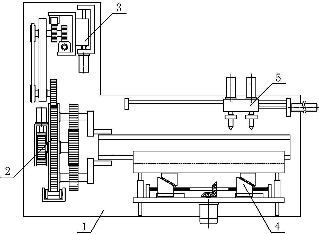
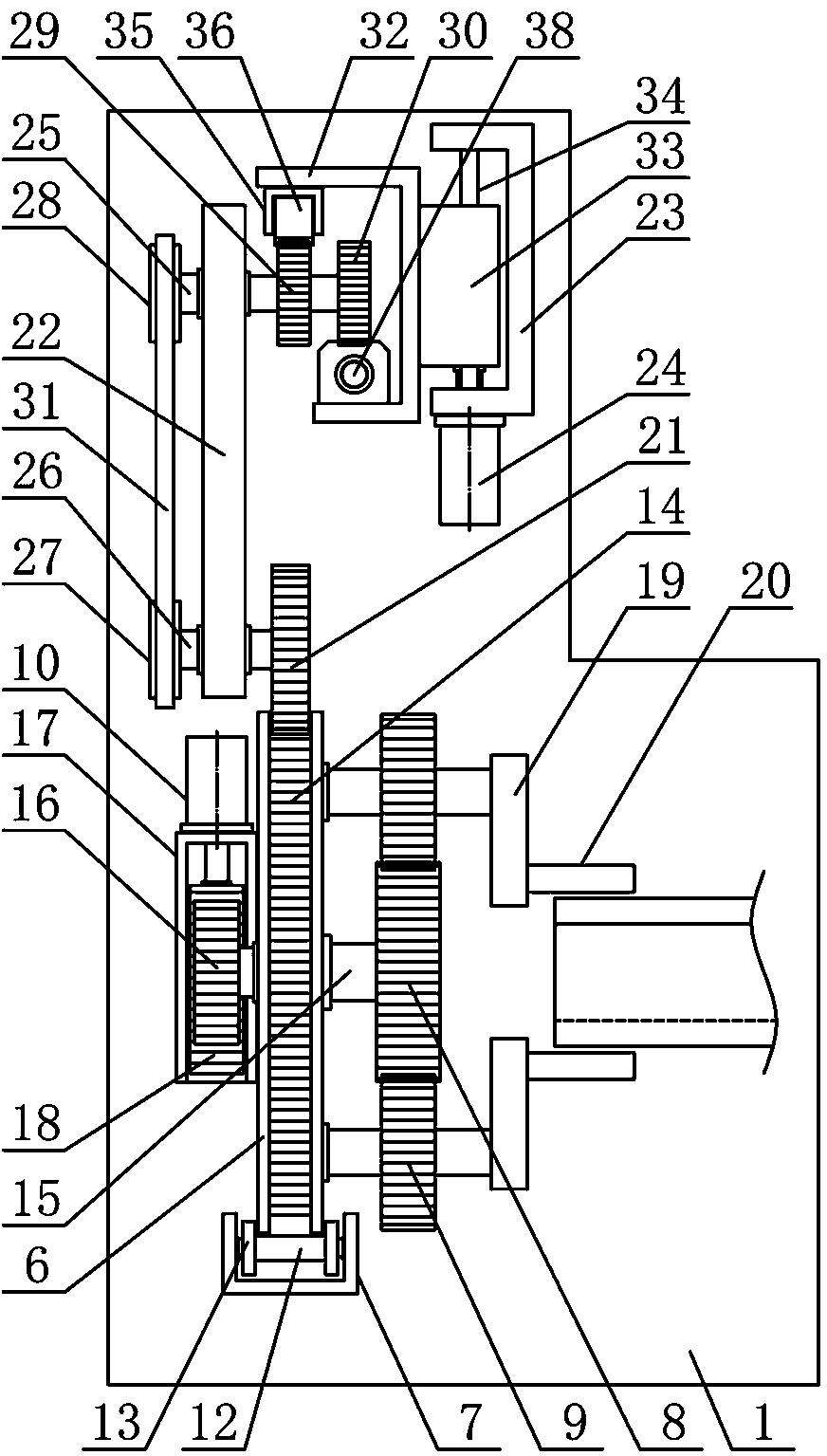
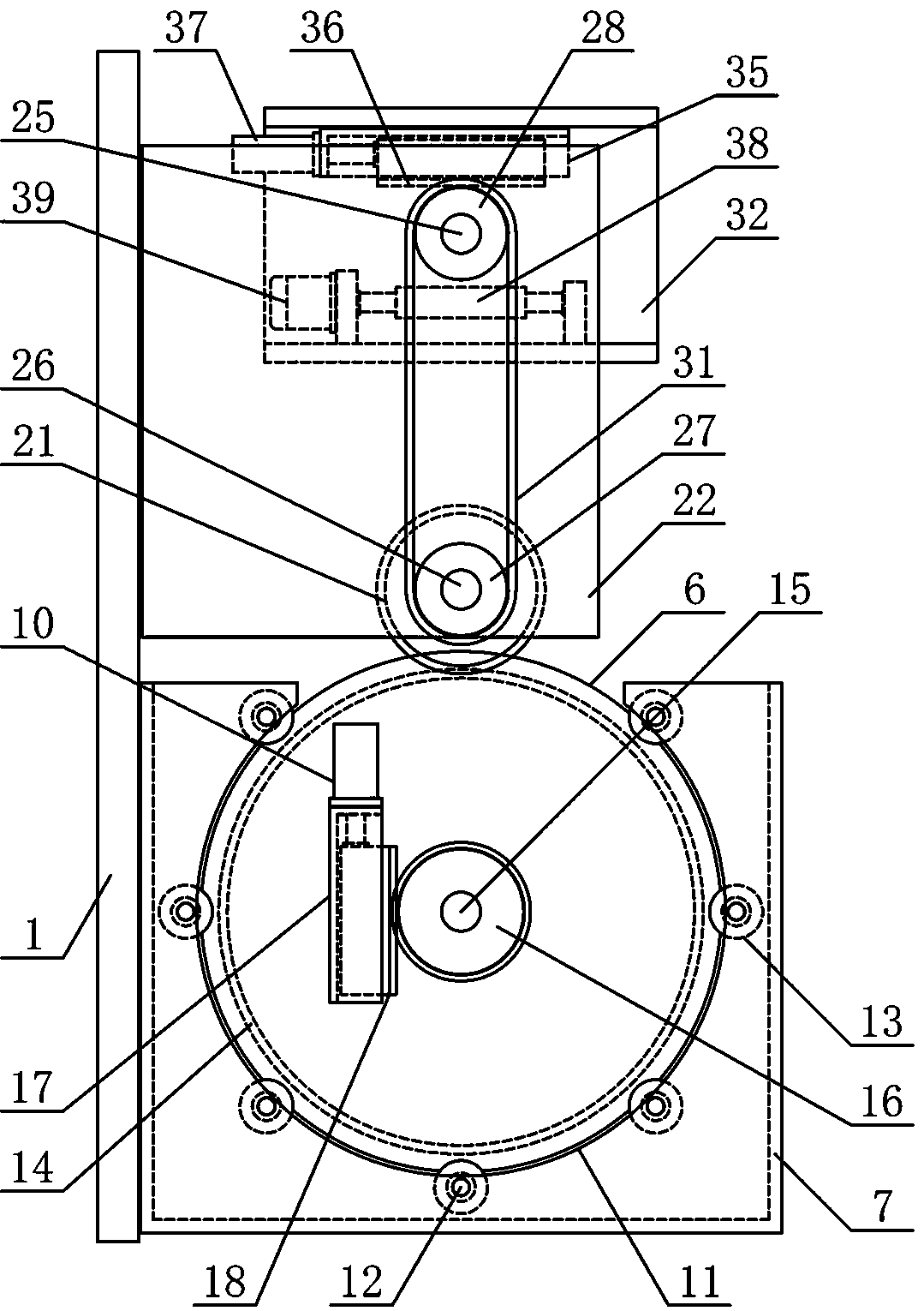
[0021] Such as figure 1 As shown, a metal shaft tube processing device of the present invention includes a processing bracket 1, a tube clamping mechanism 2, a driving mechanism 3, a tube releasing mechanism 4, and a processing mechanism 5. The driving mechanism 3 and the tube clamping mechanism 2 are vertically erected from top to bottom. It is directly arranged on one side of the processing support 1, the pipe releasing mechanism 4 is horizontally arranged on the processing frame 1 on the side of the clamping pipe mechanism 2, and the processing mechanism 5 is horizontally arranged on the processing frame 1 on the upper side of the pipe releasing me...


PUM


Abstract

The invention discloses a machining device for metallic shaft tubes, and belongs to the field of mechanical equipment for tube machining. According to the machining device, a driving mechanism and a pipe clamping mechanism are arranged at one side of a machining support in sequence; a machining mechanism is horizontally arranged on the machining support at the upper side of a pipe holding mechanism; a machining rotary plate is vertically arranged at the upper side of a bearing plate support; the machining support at the upper side of the bearing plate support is fixedly provided with a drivingsupport vertically; a pipe holding bearing plate is horizontally arranged at the upper side of an adjusting support seat; a pipe holding slot being of a V-shaped structure is horizontally formed in the pipe holding bearing plate; the output end of a horizontal moving air cylinder is fixedly connected with the middle part of one side of a machining guide plate; and the upper side of the machiningguide plate is vertically and fixedly provided with a punching air cylinder and a slotting air cylinder in sequence in the horizontal direction. The machining device is reasonable in structural designand high in machining automation degree, can efficiently and accurately perform punching and slotting in sequence on the metallic shaft tubes having various sizes, and meets the needs of production and use.

Description

technical field [0001] The invention belongs to the field of pipe material processing machinery and equipment, and in particular relates to a metal shaft tube processing device, which is mainly used in the continuous production and processing of metal shaft tubes. Background technique [0002] Shaft tube refers to a tubular workpiece with a shaft structure. The shaft tube is a necessary material for mechanical transmission equipment. The shaft tube is mainly used in the main components of the transmission system that transmits motion and energy such as automobiles and ships. The shaft tube can be divided into stepped shaft tube and Eccentric shaft tubes can also be divided into solid shaft tubes and hollow shaft tubes. In the process of producing and processing the shaft tube workpiece, in order to install, connect and fix the shaft tube in the subsequent process, the shaft tube needs to be punched and grooved separately. During the manufacturing process of the existing shaf...

Claims


Application Information

Patent Timeline
IPC IPC(8): B21D28/28B21D28/02B21D28/00B21D43/00B21D43/04B21D43/14
CPCB21D28/002B21D28/02B21D28/28B21D43/003B21D43/04B21D43/14
Inventor 黄明珠
Owner 江苏润森管业有限公司
Why Eureka
Try Eureka