
Square strip material curved surface machining tool

A technology of surface processing and square strip, applied in the field of square strip material processing equipment, can solve the problems of prolonging the processing time of square strip material, reducing the frequency of tool disassembly, and reducing the workload, etc., so as to prolong the processing time, reduce the frequency of disassembly, The effect of reducing workload

Pending Publication Date: 2019-12-20
RES INST OF ZHEJIANG UNIV TAIZHOU
View PDF0 Cites 1 Cited by
  • Summary
  • Abstract
  • Description
  • Claims
  • Application Information

AI Technical Summary

Problems solved by technology

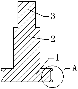
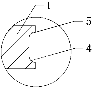
[0006] Beneficial effects of the present invention: the curved surface processing tool for square bar material of the present invention, by processing the upper and lower rounded cutting edges on the upper and lower ends of the main cutting edge, realizes the adjustment of the main cutting edge to the curved surface of the workpiece. Machining, through the chamfering of the upper and lower curved surfaces of the workpiece through the lower rounded cutting edge and the upper rounded cutting edge, it realizes the integration of multiple functions, and can process a variety of curved surfaces with one tool, thereby reducing the need for The disassembly frequency of the tool reduces the workload and error rate, thereby improving the work efficiency and the use effect is good. It solves the problem that the curved surface processing tool used for the existing square bar can only process one kind of curved surface at a time. Then, when processing other shapes of curved surfaces, it is necessary to remove the tool and replace it with a new tool, so that the tool needs to be replaced frequently, the operation is simple, the processing time of the other strip is prolonged, and the work efficiency is low.

Method used


Image

  • Square strip material curved surface machining tool
  • Square strip material curved surface machining tool

Examples


Embodiment Construction

[0011] Before describing the embodiments in detail, it should be understood that the present invention is not limited to the detailed structures or arrangements of elements described herein below or in the accompanying drawings. The present invention can be implemented in other ways. Also, it should be understood that the phraseology and terminology used herein are for descriptive purposes only and should not be interpreted as limiting. The terms "including", "comprising", "having" and similar expressions used herein are meant to include the items listed thereafter, their equivalents and other additional items. In particular, when "a certain element" is described, the present invention does not limit the number of the element to one, but may also include a plurality.

[0012] see figure 1 and figure 2 , the present invention provides a technical solution: a curved surface processing tool for square bar material, including a main cutting edge 1, the upper end of the main cu...


PUM


Abstract

The invention provides a square strip material curved surface machining tool. A main cutting edge is included. The upper end of the main cutting edge is integrally connected with a tool rod. The upperend of the tool rod is integrally connected with a tool handle. Circular beads are made at the upper end and the lower end of the main cutting edge, a lower circular bead cutting edge and an upper circular bead cutting edge are included correspondingly, and the upper circular bead cutting edge is located above the lower circular bead cutting edge. The upper circular bead cutting edge and the lower circular bead cutting edge are machined at the upper end and the lower end of the main cutting edge correspondingly, and the main cutting edge machines the appearance curved surface of a workpiece.Through workpiece upper and lower curved surface chamfer machining via the lower circular bead cutting edge and the upper circular bead cutting edge, multiple functions are integrated, one tool can beused for machining multiple curved surfaces, accordingly, the tool detaching frequency is reduced, and the workload is reduced; and the error rate is reduced, accordingly, the work efficiency is improved, and the usage effect is good.

Description

technical field [0001] The invention relates to a curved surface processing tool for square strips, which belongs to the field of square strip processing equipment. Background technique [0002] In the prior art, the existing square strip refers to cutting and processing the wood to support small strips of wood with a square cross-section to process some small wooden products, such as chopsticks and shoe brushes. handles, wooden tickles, bookmarks and more. [0003] When the existing square strips are processed on curved surfaces, the square strips are generally fixed on the machine tool, and the tool is clamped by the chuck on the machine tool, and then the curved surface of the square strip is processed by the tool. However, now The curved surface processing tools used in some square materials can only process one type of curved surface at a time, and then when processing other shapes of curved surfaces, the tool needs to be removed and replaced with a new tool, which req...

Claims


Application Information

Patent Timeline
Patent Type & Authority Applications(China)
IPC IPC(8): B27G13/00
CPCB27G13/00
Inventor 李广平王维镝吴日远陈俊廷王维锐
Owner RES INST OF ZHEJIANG UNIV TAIZHOU
Learn More