
Safety accelerator rotating brake

An accelerator and safety technology, which is applied to the safety device of the power unit control mechanism, the automatic starting device, the tractor, etc., can solve the problems of insensitivity, easy to step on the wrong accelerator and brake, traffic accidents, etc., and achieve the goal of reducing friction Effect

Pending Publication Date: 2019-12-20
刘金保
View PDF0 Cites 0 Cited by
  • Summary
  • Abstract
  • Description
  • Claims
  • Application Information

AI Technical Summary

Problems solved by technology

[0003] Traditional car brakes and accelerators use two independent pedals, and the same foot is alternately completed to control the car, and the brakes and accelerators of motor vehicles are two separate control systems. , When the driver has no time to turn his foot from the accelerator pedal to the brake pedal to step on the brake or because of panic, fatigue, or inattention, he often uses the accelerator as a brake, which leads to serious traffic accidents
And for novices who are relatively unfamiliar with vehicle control, sometimes they don’t know whether they are stepping on the accelerator or the brake, and they don’t know if they step on the wrong one. When an emergency occurs, the eyes and hands are often too tense, distracting most Energy, coupled with the sluggish feeling on the feet, it is easy to step on the wrong gas pedal and brake, resulting in traffic accidents

Method used


Image

  • Safety accelerator rotating brake
  • Safety accelerator rotating brake
  • Safety accelerator rotating brake

Examples


Embodiment 1

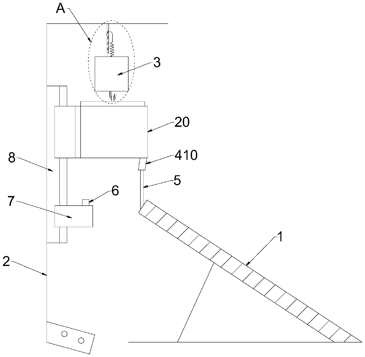
[0039]The safety accelerator brake of the present invention includes an accelerator pedal 1, a bracket 2 is arranged in front of the accelerator pedal 1, and a reset device 3 located above the accelerator pedal 1 is arranged on the bracket 2, and the lower end of the reset device 3 is connected with a liftable retractable 20, the retractor 20 is provided with a connection belt 5, the lower end of the connection belt 5 is connected to the accelerator pedal 1, and the travel switch 6 is arranged below the retractor 20, and the travel switch 6 is electrically connected with the electronic brake.

[0040] After adopting the above-mentioned technical scheme: the present invention is connected with connecting belt 5 at the upper end of accelerator pedal 1, and the other end of connecting belt 5 is arranged on the retractor 20, and the function of retractor 20 is identical with the retractor 20 of automobile safety belt , but part of its structure has been cut and optimized. The funct...

Embodiment 2

[0042] This embodiment is further optimized on the basis of Embodiment 1 as follows: the lower end of the retractor 20 is provided with an inclined guide port 410 , and the connecting belt 5 is connected to the accelerator pedal 1 through the guide port 410 .

[0043] After adopting the above-mentioned technical scheme: the guide opening 410 is arranged obliquely, because when the accelerator pedal 1 is stepped on, the movement direction of the accelerator pedal 1 is not vertically downward, but inclined, and the guide opening 410 is parallel to the movement direction of the pedal, which is convenient to reduce Frictional force during the movement of the connecting belt 5.

Embodiment 3

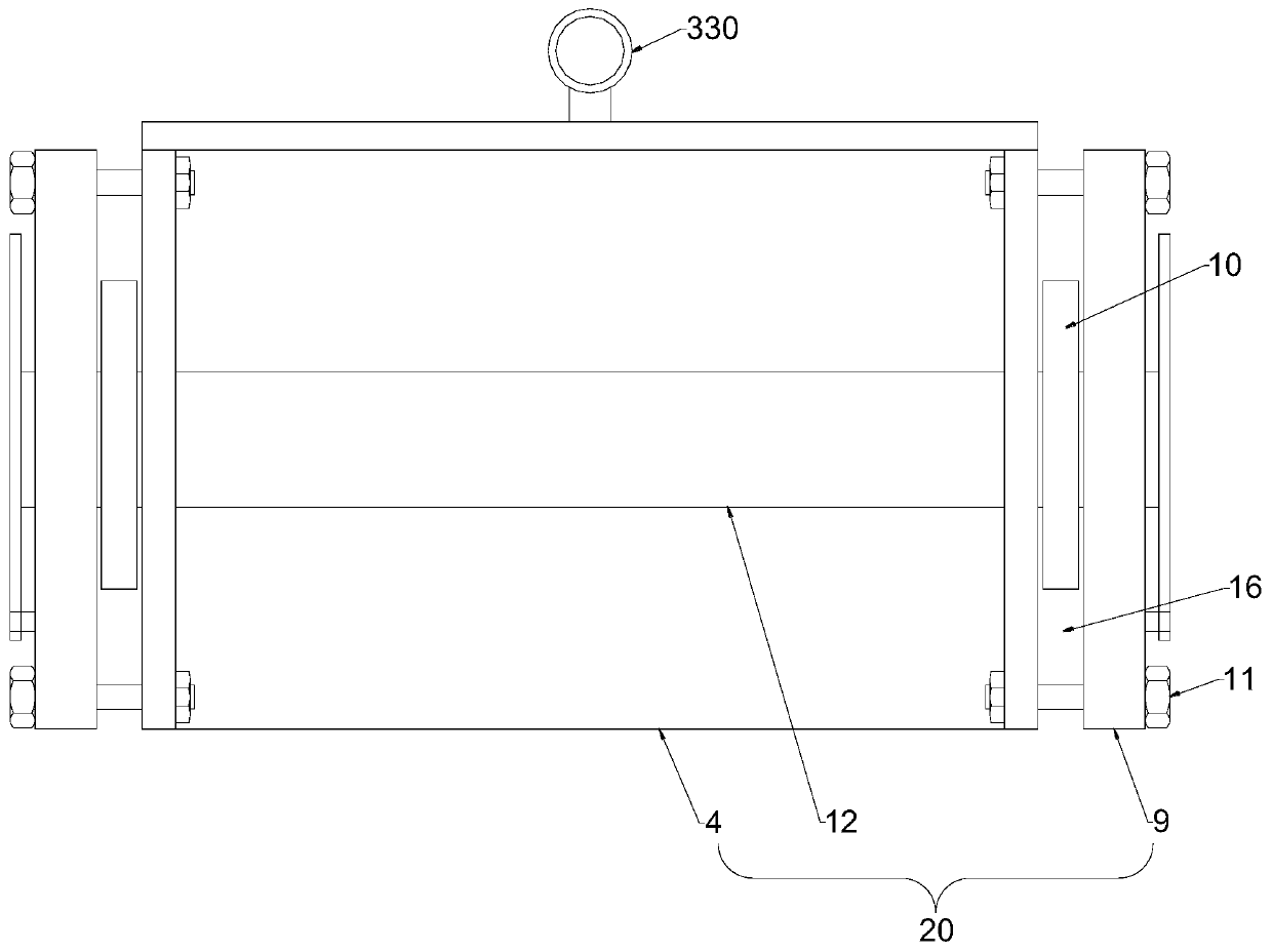
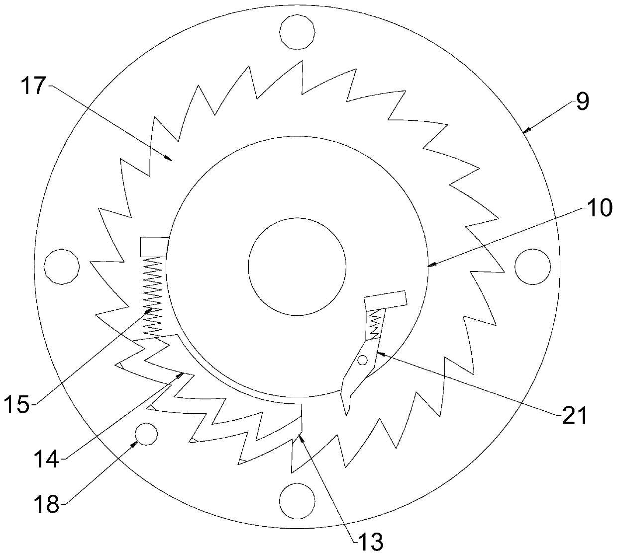
[0045] This embodiment is further optimized on the basis of Embodiment 1 as follows: the retractor 20 includes a frame 4, a rotating shaft 12 and an inner ratchet 9; two inner ratchets 9 are arranged on the left and right sides of the frame 4 respectively, There is a first gap 16 between the frame 4, the two ends of the rotating shaft 12 pass through the frame 4 and the inner ratchet 9 in turn, the rotating shaft 12 is sleeved with a turntable 10 located in the inner ratchet 9, between the inner ratchet 9 and the turntable 10 A bottom plate 13 is provided on the outer edge of the turntable 10 provided with a second gap 17, the bottom plate 13 is located in the first gap 16 and fits with the first gap 16, and the side wall of the bottom plate 13 is provided with a cam block 14 located in the second gap 17 , the shape of the cam block 14 is compatible with the inner ratchet 9, and one side of the cam block 14 along the moving direction is provided with a connecting spring 15, and...


PUM


Abstract

The invention discloses a safety accelerator rotating brake, and relates to the technical field of brake accelerator combined devices. The safety accelerator rotating brake aims to avoid the situationthat an automobile driver mistakenly treats an accelerator as a brake under an emergency situation to cause traffic accidents. The safety accelerator rotating brake comprises an accelerator pedal, asupport is arranged in front of an accelerator pedal, a reset device located above the accelerator pedal is arranged on the support, a liftable retractor is connected to the lower end of the reset device, a connecting belt is arranged in the retractor, the lower end of the connecting belt is connected with the accelerator pedal, a travel switch is arranged below the retractor, and the travel switch is electrically connected with an electronic brake.

Description

technical field [0001] The invention relates to the technical field of a brake accelerator combination device, in particular to a safety accelerator rotary brake. Background technique [0002] Automobile is a kind of main means of transportation in modern society. With the improvement of people's living standard and the quickening pace of life, the development of automobile is more rapid. But at the same time, traffic accidents also increased thereupon. [0003] Traditional car brakes and accelerators use two independent pedals, and the same foot is alternately completed to control the car, and the brakes and accelerators of motor vehicles are two separate control systems. , When the driver has no time to turn his foot from the accelerator pedal to the brake pedal to step on the brake or because of panic, fatigue, and inattention, he often uses the accelerator as a brake, resulting in serious traffic accidents. And for novices who are relatively unfamiliar with vehicle con...

Claims


Application Information

Patent Timeline
IPC IPC(8): B60K26/02B60K28/14B60T7/12
CPCB60K26/02B60K28/14B60T7/12
Inventor 刘金保
Owner 刘金保
Learn More