an electromagnetic launcher

An electromagnetic and circuit technology, applied in the field of electromagnetic emission devices, can solve the problems of low utilization rate of the magnetic field on both sides of the motor stator, complex suspension structure, etc., and achieve the effects of intuitive and convenient recording, strong operability, and improved braking ability

Active Publication Date: 2021-07-23
NAT UNIV OF DEFENSE TECH
View PDF0 Cites 0 Cited by
  • Summary
  • Abstract
  • Description
  • Claims
  • Application Information

AI Technical Summary

Problems solved by technology

[0005] In view of the deficiencies in the prior art, the present invention proposes an electromagnetic emission device, which solves the technical problems in the prior art that the suspension structure is complex and the utilization rate of the magnetic field on both sides of the motor stator is low

Method used


Image

  • an electromagnetic launcher
  • an electromagnetic launcher
  • an electromagnetic launcher

Examples


Embodiment Construction

[0028] In order to enable those skilled in the art to better understand the technical solution of the present invention, the present invention will be further described in detail below in conjunction with the accompanying drawings.

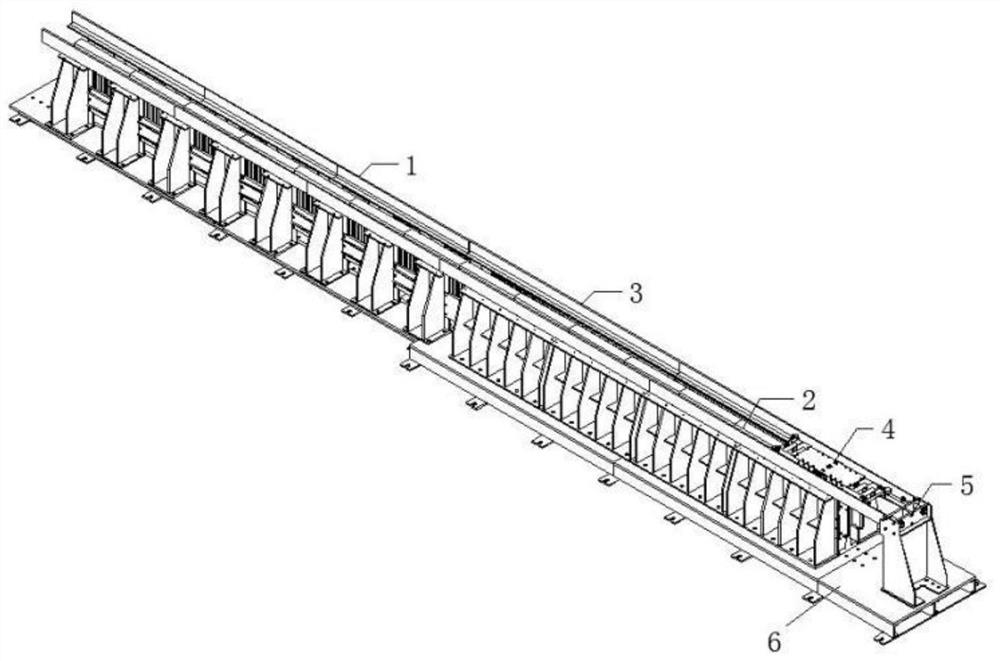
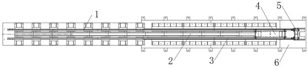
[0029] Such as figure 1 , figure 2 As shown, an electromagnetic emission device includes a motor module and a control system module for controlling the motor module, the motor module includes a platform base 6, and the platform base 6 is provided with a support track 3 and a motor stator 2. The motor stator 2 is located inside the support rail 3, and the support rail 3 is provided with a mover body 4 that can be driven by the motor stator 2 to move along the inside of the support rail 3. The support The track 3 is provided with a suspension track 1 that can interact with the mover car body 4 to suspend the mover car body 4, and the suspension track 1 includes induction plates 7 symmetrically arranged on both sides of the motor stator 2, When th...


PUM


Abstract

The present invention relates to the field of electromagnetic emission technology, in particular to an electromagnetic emission device, comprising a motor module and a control system module for controlling the motor module, the motor module includes a platform base, and the platform base is provided with a support track and motor stator, the motor stator is located on the inner side of the support track, the mover car body that can be driven by the motor stator to move along the inner side of the support track is provided on the support track, and the support track is provided with There is a suspension track that can interact with the mover car body to suspend the mover car body. The suspension track includes induction plates symmetrically arranged on both sides of the motor stator. When the mover car body moves to the When the suspension track is used, the induction plate is located between the support track and the mover car body, and the control system module is electrically connected to the motor stator. The invention has a simple and compact structure, and has the characteristics of high magnetic field utilization rate and high traction efficiency.

Description

technical field [0001] The invention relates to the technical field of electromagnetic emission, in particular to an electromagnetic emission device. Background technique [0002] Electromagnetic launch technology is a brand new launch technology, which uses electromagnetic energy to accelerate objects to a very high launch speed; moreover, the time required for electromagnetic launch technology is very short, generally a few milliseconds to a dozen milliseconds. Compared with traditional chemical energy and mechanical energy emission technologies, electromagnetic energy emission technology has a series of advantages such as fast emission speed, good controllability, excellent performance, and high emission efficiency. [0003] There are many kinds of launching devices in electromagnetic launching technology, which can be divided into guide rail type, coil type and reconnection type according to different launching devices. Among them, the launching device of the rail-type ...

Claims


Application Information

Patent Timeline
Patent Type & Authority Patents(China)
IPC IPC(8): B60L13/06B60L13/10B60L7/28E01B25/00E01B25/30
CPCB60L7/28B60L13/06B60L13/10E01B25/00E01B25/30E01B25/305
Inventor 李杰崔鹏周丹峰余佩倡陈强郭昭宇
Owner NAT UNIV OF DEFENSE TECH
Why Eureka
Try Eureka