Supporting roll device dragged by superconductive outer rotor electric machine

A technology for external rotor motors and back-up rolls, which is applied in the direction of counter pressure devices, metal processing equipment, metal rolling, etc., and can solve problems such as increased difficulty in spatial arrangement of rolling mills or straightening machines, increased maintenance costs, and deformation of back-up rolls. Achieve the effect of facilitating industrial application and solving the difference in temperature field

Pending Publication Date: 2018-11-23
TAIYUAN UNIVERSITY OF SCIENCE AND TECHNOLOGY
View PDF0 Cites 3 Cited by
  • Summary
  • Abstract
  • Description
  • Claims
  • Application Information

AI Technical Summary

Problems solved by technology

[0002] At present, the rolling mills and straightening machines in the continuous rolling production line at home and abroad all adopt staggered backup rolls, that is, passive backup rolls are used to support the work rolls, which have the following disadvantages: ① With the increase of rolling width, the upper , The upper and lower back-up rolls of

Method used


Image

  • Supporting roll device dragged by superconductive outer rotor electric machine
  • Supporting roll device dragged by superconductive outer rotor electric machine

Examples


Embodiment Construction

[0014] The present invention will be described in detail below through preferred embodiments in conjunction with the accompanying drawings.

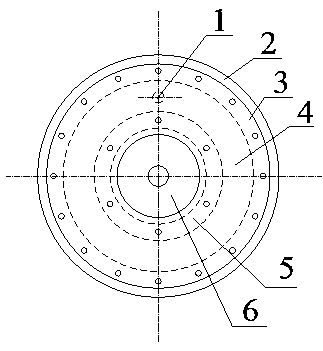
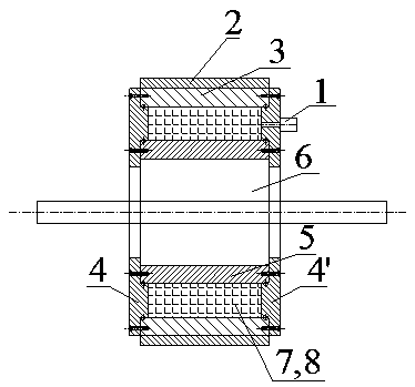
[0015] Arrange the device of the present invention in a staggered manner on the upper and lower work rolls of the strip, replace the staggered backup rolls in the prior art, and support them in a staggered manner; as figure 1 As shown, the outer cylinder 3, the left and right annular end caps 4, 4' and the inner cylinder 5 are assembled into an annular cavity 8, and the 3D printing space support structure 7 is loaded into the annular cavity 8, and the 3D printing space support 7 It is a space truss structure printed by a 3D printer to ensure a reasonable supporting effect. The annular cavity 8 is evacuated through the vacuum check valve 1 to achieve a heat-resistant vacuum environment. A superconducting outer rotor motor stator and outer rotor form a superconducting The magnetic levitation structure, by controlling the stator current of ...


PUM


Abstract

The invention provides a supporting roll device dragged by a superconductive outer rotor electric machine, and belongs to the technical field of metallurgical engineering. The supporting roll device is characterized by comprising a vacuum check valve, a roll sleeve, an outer cylinder body, an inner cylinder, left and right annular end caps, the superconductive outer rotor electric machine and a 3Dprinting spatial support. According to connection relations, the superconductive outer rotor electric machine is sleeved with the inner cylinder, the outer circumference of the inner cylinder is sleeved with the outer cylinder body, the left and right annular end caps are connected with the inner cylinder and the outer cylinder body through left and right bolt groups so as to form an annular inner cavity, and the 3D printing spatial support is installed in the annular inner cavity; the outer circumferential surface of the outer cylinder body is sleeved with the roll sleeve, the vacuum check valve communicated with the annular inner cavity is installed in the middle of the right annular end cap, and the annular inner cavity is vacuumized through the vacuum check valve. According to the supporting roll device, a thermal-resistant vacuum environment is achieved, the 3D printing space supporting structure is arranged in the cavity, and a reasonable supporting effect is ensured; a superconductive magnetic suspension structure is formed between a stator and an outer rotor of the superconductive outer rotor electric machine, by adjusting the motor stator current, the supporting and carrying capacity is controlled, and the effect of the supporting roll is achieved.

Description

technical field [0001] The invention belongs to the technical field of metallurgical engineering, and in particular relates to a support roller device driven by a superconducting outer rotor motor. Background technique [0002] At present, the rolling mills and straightening machines in the continuous rolling production line at home and abroad all adopt staggered backup rolls, that is, passive backup rolls are used to support the work rolls, which have the following disadvantages: ① With the increase of rolling width, the upper , The upper and lower back-up rolls of the lower work roll receive uneven distribution of rolling force or straightening force, resulting in deformation of the back-up rolls, increased rotation wear, and increased maintenance costs; ②As the strength of the rolled material increases, the back-up roll As the diameter increases, the spatial arrangement of the rolling mill or leveler becomes more difficult. Contents of the invention [0003] The purpos...

Claims


Application Information

Patent Timeline
IPC IPC(8): B21B29/00
CPCB21B29/00
Inventor 李昕涛李子良黄庆学杨亚坤张文成
Owner TAIYUAN UNIVERSITY OF SCIENCE AND TECHNOLOGY
Why Eureka
Try Eureka