Railway vehicle sleeper beam, underframe and underframe welding method
What is AI technical title?
AI technical title is built by PatSnap AI team. It summarizes the technical point description of the patent document.
A rail vehicle and corbel technology, which is applied to the underframe, welding equipment, welding equipment, etc., can solve the problems of welding deformation, cost, and long working hours, and achieve the effect of reducing welding deformation and improving connection strength
Active Publication Date: 2019-12-20
ZHUZHOU ELECTRIC LOCOMOTIVE CO
View PDF9 Cites 9 Cited by
Summary
Abstract
Description
Claims
Application Information
AI Technical Summary
This helps you quickly interpret patents by identifying the three key elements:
Problems solved by technology
Method used
Benefits of technology
Problems solved by technology
With the full-length floor structure, the welds between the corbel beam and the underframe floor are concentrated on one side, which is easy to cause welding deformation
In addition, the process gap is usually set on the lower plane of the corbel. After the cover plate and the corbel are welded, the underframe of the car body needs to be machined as a whole because of the need to smooth the weld seams concentrated on the lower plane, which occupies a large area of the underframe. The working hours of large stations are long and cost more manpower
Method used
Image
Click on the blue label to locate the original text in one second.
Reading with bidirectional positioning of images and text.
Examples
Embodiment 1
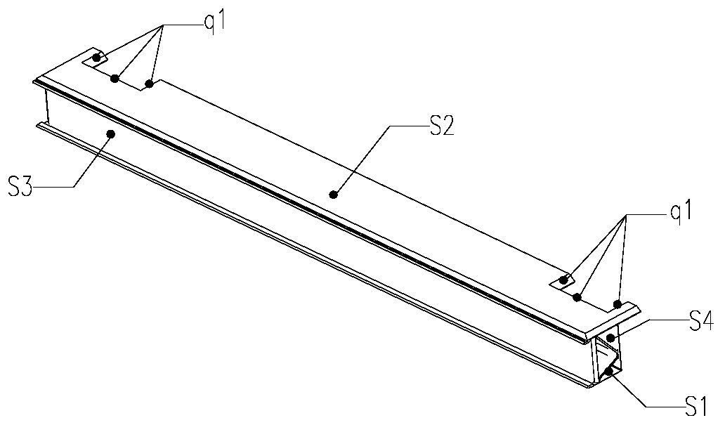
[0063] The invention discloses a rail vehicle corbel, wherein the rail vehicle corbel includes a corbel main body, an end cover plate 302 and a floor connecting profile 307 .
[0064] The floor connecting profiles 307 are respectively welded on the longitudinal two sides of the corbel main body, and the outer sides of the floor connecting profiles 307 are respectively welded with the short floor 305 and the long floor 306 of the chassis, the top surface of the corbel main body is flush with the top surface of the chassis floor, and the bottom The frame floor adopts a non-through-length floor structure, that is, the floor is disconnected at the rail vehicle corbel.
[0065] That is, the floor connecting profile is welded inwardly with the main body of the corbel and outwardly with the floor of the chassis. Connect them in sequence according to the order of the chassis floor, the floor connection profile, and the main body of the corbel.
[0066] The two transverse ends of the ...
Embodiment 2
[0072] In the second embodiment provided by the present invention, the structure of the rail vehicle bolster in this embodiment is similar to that of the rail vehicle bolster in the first embodiment, and the similarities will not be repeated, and only the differences will be introduced.
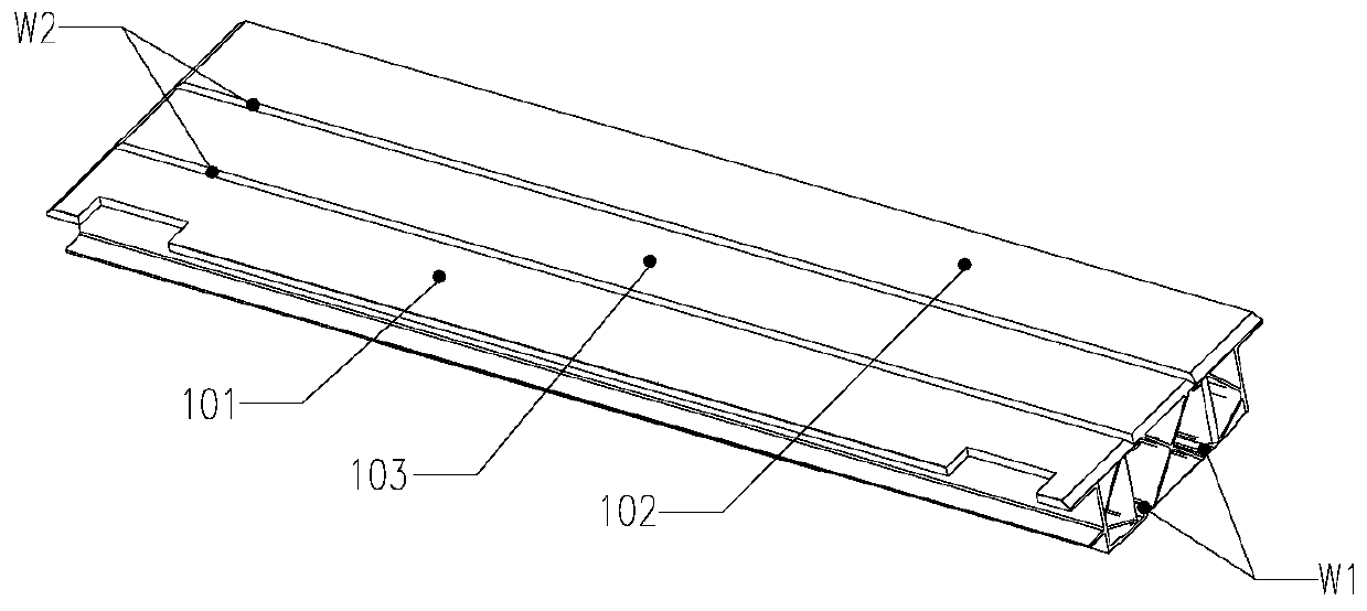
[0073] In this embodiment, the present invention discloses that the main body of the bolster includes a first side bolster 101, a second side bolster 102 and a middle bolster 103, and the first side bolster 101 and the second side bolster 102 are respectively welded in the middle The longitudinal two sides of corbel 103.
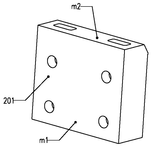
[0074] Further, the present invention discloses that the rail vehicle bolster further includes an anti-roll structure 104 , and the anti-roll structure 104 includes an anti-roll mounting seat 201 and a positioning thread block 202 .
[0075] An installation notch is opened on the bottom surface of the first side bolster 101 , and the anti-rollover mounting seat 201 is welde...
Embodiment 3
[0095] The present invention provides an underframe, including the rail vehicle bolster in any one of the above embodiments.
[0096] Since the underframe disclosed in the present invention includes the rail vehicle bolster in any one of the above embodiments, the beneficial effects of the above rail vehicle bolster are included in the underframe disclosed in the present invention.
PUM
Abstract
The invention discloses a railway vehicle sleeper beam, an underframe and an underframe welding method. The railway vehicle sleeper beam comprises a sleeper beam main body, end cover plates and floorconnecting profiles welded on the two longitudinal sides of the sleeper beam main body; the outer sides of the floor connecting profiles at the two longitudinal ends of the sleeper beam main body arerespectively welded to a floor, and the top surface of the sleeper beam main body is flush with the top surface of the floor; the two sides of the top surface of the sleeper beam main body are provided with process notches; an inner side rib plate of the sleeper beam main body is welded to the inner side of an underframe side beam through a vertical welding seam between the inner side rib plate and the underframe side beam, the end cover plates cover the process notches, the peripheries of the end cover plates are welded to the sleeper beam main body, the top surface of the sleeper beam main body is welded to the underframe side beam through a longitudinal welding seam between the top surface of the sleeper beam main body and the underframe side beam, a sleeper beam outer side rib plate ofthe sleeper beam main body is welded to the underframe side beam through a vertical welding seam between the sleeper beam outer side rib plate and the underframe side beam, and the bottom face of thesleeper beam main body is welded to the underframe side beam through a longitudinal welding beam between the sleeper beam main body and the underframe side beam. The process notches are formed in thetop surface of the sleeper beam main body, the floor is arranged in blocks, the sleeper beam and the welding beams of the floor are prevented from being concentrated on one side, and welding deformation is reduced.
Description
technical field [0001] The invention relates to the technical field of rail transit car underframes, in particular to a rail vehicle bolster made of aluminum alloy, an underframe and a welding method for the underframe. Background technique [0002] The bolster is the main force-bearing part of the car body underframe structure. It plays the role of connecting the bogie and transmitting the longitudinal compression force and traction force. It is the key structure for power transmission to realize the safe driving of the vehicle. [0003] At present, when the corbel is connected to the floor of the underframe, the upper plane of the corbel is directly contacted with the lower surface of the full-length floor for installation. The connection between the bolster and the underframe side sill is realized through the vertical welds on the inner plane of the bolster and the underframe side sill, and the welds along the longitudinal direction of the car body are connected through t...
Claims
Application Information
Patent Timeline
Application Date:The date an application was filed.
Publication Date:The date a patent or application was officially published.
First Publication Date:The earliest publication date of a patent with the same application number.
Issue Date:Publication date of the patent grant document.
PCT Entry Date:The Entry date of PCT National Phase.
Estimated Expiry Date:The statutory expiry date of a patent right according to the Patent Law, and it is the longest term of protection that the patent right can achieve without the termination of the patent right due to other reasons(Term extension factor has been taken into account ).
Invalid Date:Actual expiry date is based on effective date or publication date of legal transaction data of invalid patent.

