Mechanical automatic feeding mechanism

A feeding mechanism and mechanical technology, applied in the direction of solid materials, packaging, packaging items, etc., can solve problems such as reducing safety, reducing production efficiency, and increasing costs, reducing labor waste, improving safety, and increasing production efficiency. Effect

Inactive Publication Date: 2019-12-20
LANZHOU INST OF TECH
View PDF8 Cites 5 Cited by
  • Summary
  • Abstract
  • Description
  • Claims
  • Application Information

AI Technical Summary

Problems solved by technology

[0002] The general structure of the feeding device is mainly composed of conveyor belts, rollers, supporting devices, driving devices, tensioning devices, unloading devices, cleaning devices and racks. The belt feeder is a continuous feeding machine. It uses a The conveyor belt wrapped around the front and rear rollers is used as a traction and load-bearing member. The driving roller relies on friction to drive the conveyor belt to move, and drives the materials to run together, so as to achieve the purpose of conveying materials. There are many existing feeding and transportation All of them use manual feeding, and the quantitative and component transmission after feeding in the feeding mechanism needs to be completed manually, which increases the waste of manpower and labor intensity of workers, reduces safety, thereby increasing costs, and at the same time reducing Productivity

Method used


Image

  • Mechanical automatic feeding mechanism
  • Mechanical automatic feeding mechanism
  • Mechanical automatic feeding mechanism

Examples


Embodiment 1

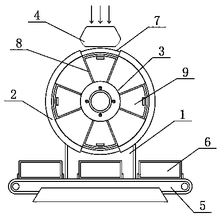
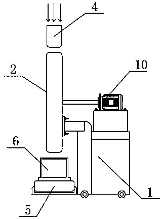
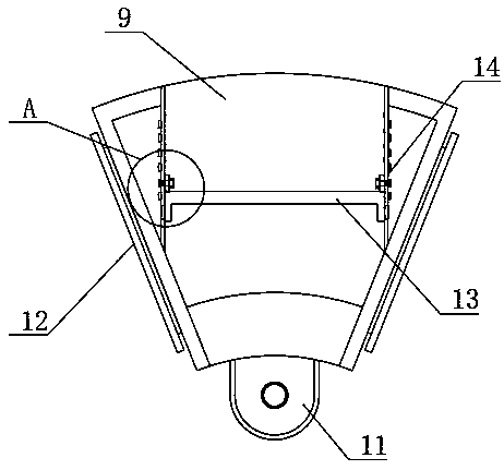
[0020] see Figure 1-5 , the present invention provides the following technical solutions: a mechanical automatic feeding mechanism, including an outer shell 2, an inlet shell 4 above the outer shell 2, and a conveyor belt assembly 5 below the outer shell 2. Material box 6, one side of outer casing 2 is provided with fixed seat 1, and fixed seat 1 and outer casing 2 are fixedly connected by fastening screw, and the upper surface of fixed seat 1 is fixedly connected with motor 10 by bolt, and in the present embodiment, motor 10 is a motor of the type SST86D1605 produced by Dongguan Morse Automation Technology Co., Ltd., the inside of the outer casing 2 is provided with a roulette body 3, and the inside of the roulette body 3 is provided with a card slot 8, and the output end of the motor 10 is connected to the roulette The body 3 is connected by transmission, and the inside of the card slot 8 is provided with a connecting box 9, and both sides of the connecting box 9 are integr...


PUM


Abstract

The invention belongs to the technical field of feeding equipment and especially relates to a mechanical automatic feeding mechanism which comprises an outer shell, a feeding hole shell above the outer shell and a conveying belt assembly under the outer shell, wherein a material collection box is clamped above the conveying belt assembly; a fixation base is disposed on one side of the outer shell;and the fixation base and the outer shell are fixedly connected by a fastening screw. According to different positions of a bearing plate which is moved according to marks inside a linkage box, a quantity of materials which can be stored in the linkage box is controlled and thus the materials in the linkage box of the fixed quantity can be smoothly conveyed into the corresponding material connection box after subsequent periodic rotation of a wheel disk body together with the linkage box; in this way, the problem that quantification and transportation of the materials are not effective enoughduring use of an original mechanical automatic feeding mechanism can be solved; and through mechanical use, manpower waste and workers' labor strength are reduced, safety is enhanced and production efficiency is also increased.

Description

technical field [0001] The invention belongs to the technical field of feeding equipment, and in particular relates to a mechanical automatic feeding mechanism. Background technique [0002] The general structure of the feeding device is mainly composed of conveyor belts, rollers, supporting devices, driving devices, tensioning devices, unloading devices, cleaning devices and racks. The belt feeder is a continuous feeding machine. It uses a The conveyor belt wrapped around the front and rear rollers is used as a traction and load-bearing member. The driving roller relies on friction to drive the conveyor belt to move, and drives the materials to run together, so as to achieve the purpose of conveying materials. There are many existing feeding and transportation All of them use manual feeding, and the quantitative and component transmission after feeding in the feeding mechanism needs to be completed manually, which increases the waste of manpower and labor intensity of worke...

Claims


Application Information

Patent Timeline
Patent Type & Authority Applications(China)
IPC IPC(8): B65B1/48B65B43/54
CPCB65B1/48B65B43/54
Inventor 张继林郭文静易湘斌王亮贾海深窦建明张军平
Owner LANZHOU INST OF TECH
Why Eureka
Try Eureka