
Automatic stacking and palletizing device

A technology of stacking and equipment, which is used in the stacking of objects, destacking, transportation and packaging of objects, etc., can solve the problems of waste of station space, no, no adjustment of the position and orientation of the material box, etc., to achieve convenience and difficulty , the effect of reducing complexity

Active Publication Date: 2019-12-20
SUZHOU JINGLAI OPTO CO LTD
View PDF12 Cites 4 Cited by
  • Summary
  • Abstract
  • Description
  • Claims
  • Application Information

AI Technical Summary

Problems solved by technology

[0002] In the prior art, the mechanical arm is often used for palletizing, but generally the accuracy of palletizing is not high, so the grabbing position of the mechanical arm does not have a device for positioning the material box, and the general material box only needs to be oriented when palletizing. It is completely consistent and can be stacked repeatedly, so the palletizing mechanism usually does not have the function of adjusting the position and orientation of the material box; but with the development of production automation, the stacked material boxes are no longer manually handled, but are handled by manipulators or other mechanisms , usually in order to ensure the free movement of the manipulator, there is a special space for the manipulator to move around the pallet of the stacking equipment. Accurate positioning, while the existing palletizing mechanism can no longer meet the requirements

Method used


Image

  • Automatic stacking and palletizing device
  • Automatic stacking and palletizing device
  • Automatic stacking and palletizing device

Examples


Embodiment

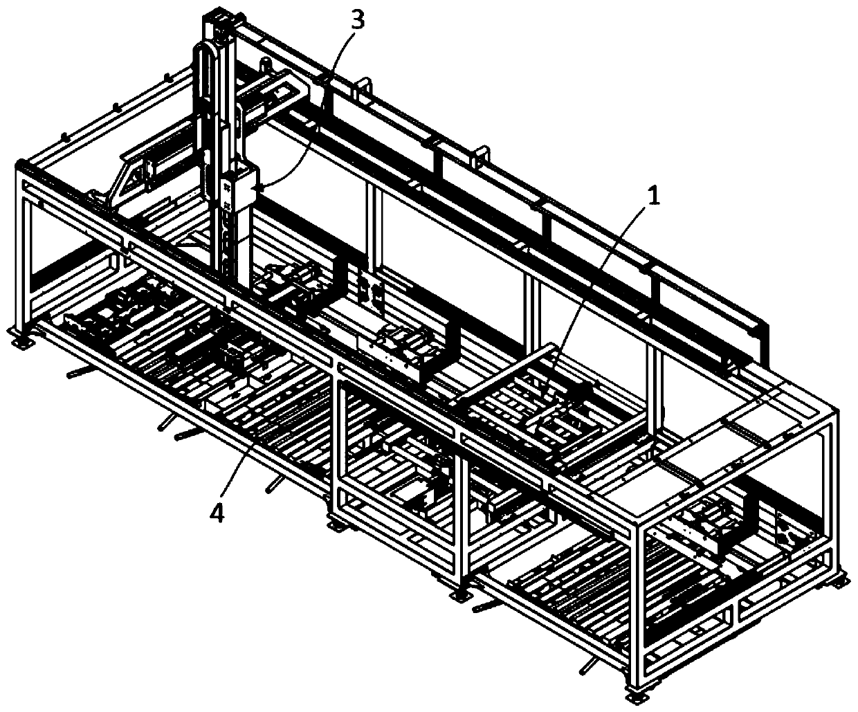
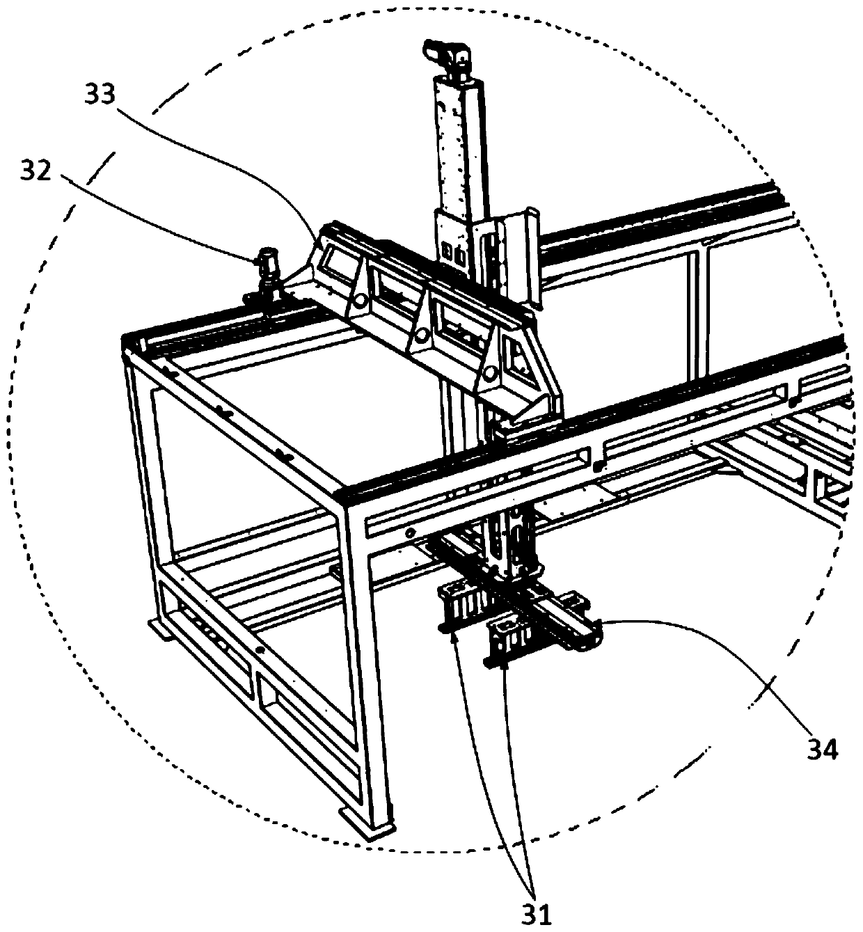
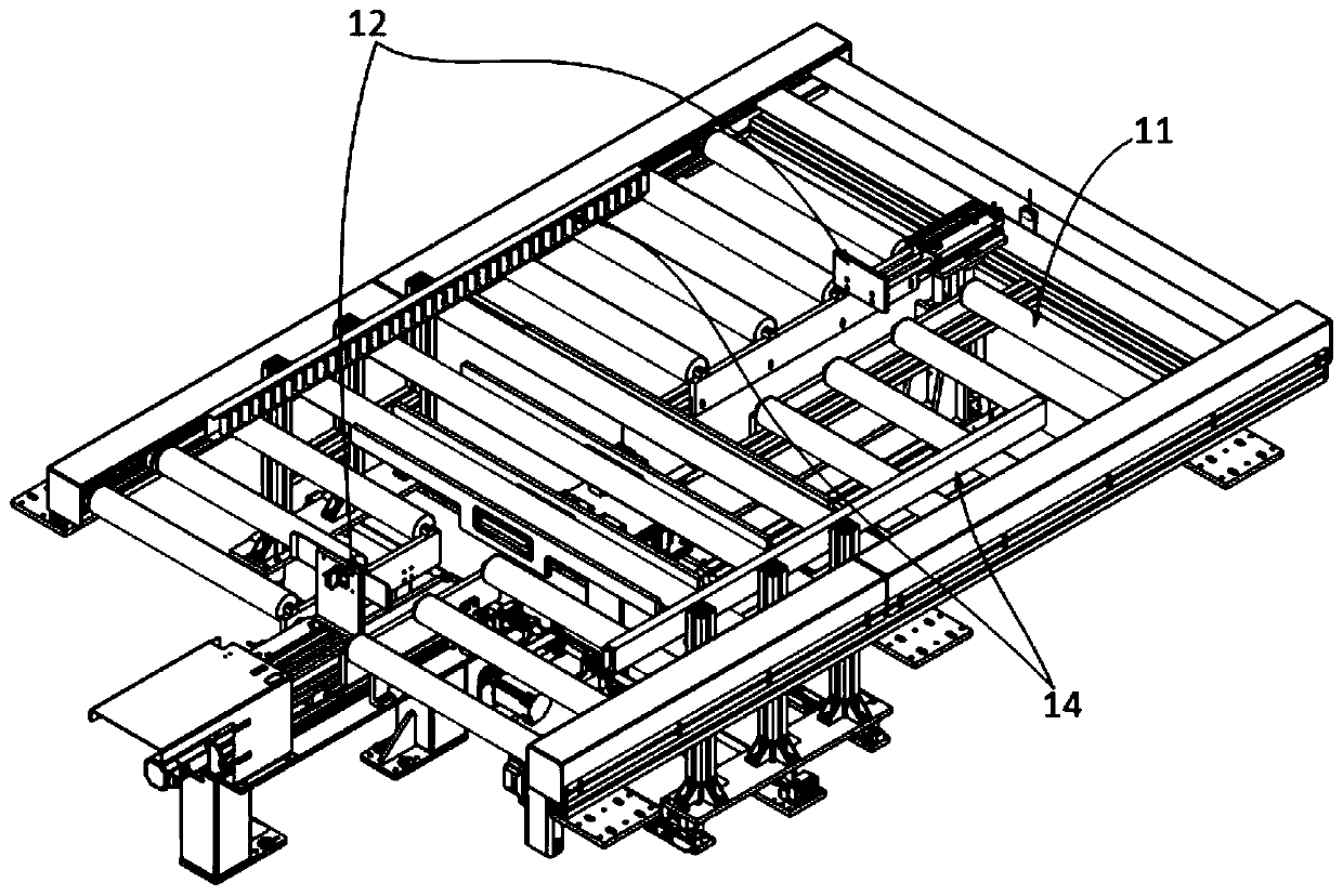
[0074] This embodiment provides an automatic stacking device, such as Figure 1-3 shown, including:

[0075] frame;

[0076] Incoming material drum line 1, used to transport the material box;

[0077] The pallet 4 is arranged on the side of the incoming material drum line 1;

[0078] Grab material conveying mechanism 3, used for grabbing material boxes from said incoming material drum line 1 and being able to stack at least 2 stacks of material boxes on said pallet 4;

[0079] The leaning mechanism is arranged at the pallet 4 and is used to push the stacked magazines so that two adjacent stacks of magazines are close to each other.

[0080] Preferably, the automatic stacking device of this embodiment, such as Figure 10 As shown, the positioning mechanism includes:

[0081] The stacking alignment plate 7 can push the stacked magazines on the pallet 4 to move under the drive of the driver.

[0082] Preferably, the automatic stacking device of the present embodiment also inc...


PUM


Abstract

The invention relates to an automatic stacking and palletizing device. The automatic stacking and palletizing device comprises a frame, a supplied material roller line, a grabbing conveying mechanismand a pallet, wherein the supplied material roller line is used for receiving material boxes and comprises a conveying line support, a plurality of rollers arranged between the two ends of the conveying line support, a pair of first push plates positioned at the two ends of the conveying line support and a pair of second push plates positioned at the two sides of the conveying line support; the material box can be switched in the X direction and the Y direction; the grabbing conveying mechanism is connected to the frame and can perform triaxial movement; the lower end of the grabbing conveyingmechanism is provided with a grabbing part for grabbing the material boxes; and the pallet is arranged below the frame and used for bearing the stacked material boxes. The material boxes can be positioned on the periphery once before mechanical arms grab the material boxes, so that each material box is at a fixed position, the difficulty of grabbing the material boxes by the mechanical arms is greatly reduced, and the complexity of a control program is reduced as well.

Description

technical field [0001] The application belongs to the technical field of automatic palletizing, and in particular relates to an automatic stacking device. Background technique [0002] In the prior art, the mechanical arm is often used for palletizing, but generally the accuracy of palletizing is not high, so the grabbing position of the mechanical arm does not have a device for positioning the material box, and the general material box only needs to be oriented when palletizing. It is completely consistent and can be stacked repeatedly, so the palletizing mechanism usually does not have the function of adjusting the position and orientation of the material box; but with the development of production automation, the stacked material boxes are no longer manually handled, but are handled by manipulators or other mechanisms , usually in order to ensure the free movement of the manipulator, there is a special space for the manipulator to move around the pallet of the stacking eq...

Claims


Application Information

Patent Timeline
IPC IPC(8): B65G61/00B65G57/20
CPCB65G57/20B65G61/00
Inventor 陈东风
Owner SUZHOU JINGLAI OPTO CO LTD
Learn More