
Cast-in-situ box girder support system and construction method thereof

A box girder, cast-in-place technology, applied in bridges, bridge materials, bridge construction, etc., can solve the problem that the steel pipe column foundation cannot be erected, erected and erected, the preloading construction of the support system is large, and the long-span Bailey beam is too long, etc. problems, to achieve obvious technical and economic benefits, reduce engineering costs, and ensure the effect of accuracy

Pending Publication Date: 2019-12-20
NINGBO UNIV
View PDF7 Cites 1 Cited by
  • Summary
  • Abstract
  • Description
  • Claims
  • Application Information

AI Technical Summary

Problems solved by technology

However, for the cast-in-place box girder with high pier with a steep terrain and a pier body height of 40m or more, the use of full-wall support not only has the disadvantages that the steel pipe column and its foundation cannot be erected or erected, and the long-span Bailey beam is too long to cause the middle There are problems such as large deflection of parts, large preloading construction of the support system, etc., and the safety is low, and the investment in materials and personnel is also large

Method used


Image

  • Cast-in-situ box girder support system and construction method thereof
  • Cast-in-situ box girder support system and construction method thereof
  • Cast-in-situ box girder support system and construction method thereof

Examples


Embodiment Construction

[0039] The present invention will be further described below in conjunction with the examples. The description of the following examples is provided only to aid the understanding of the present invention. It should be pointed out that for those skilled in the art, without departing from the principle of the present invention, some improvements and modifications can be made to the present invention, and these improvements and modifications also fall within the protection scope of the claims of the present invention.

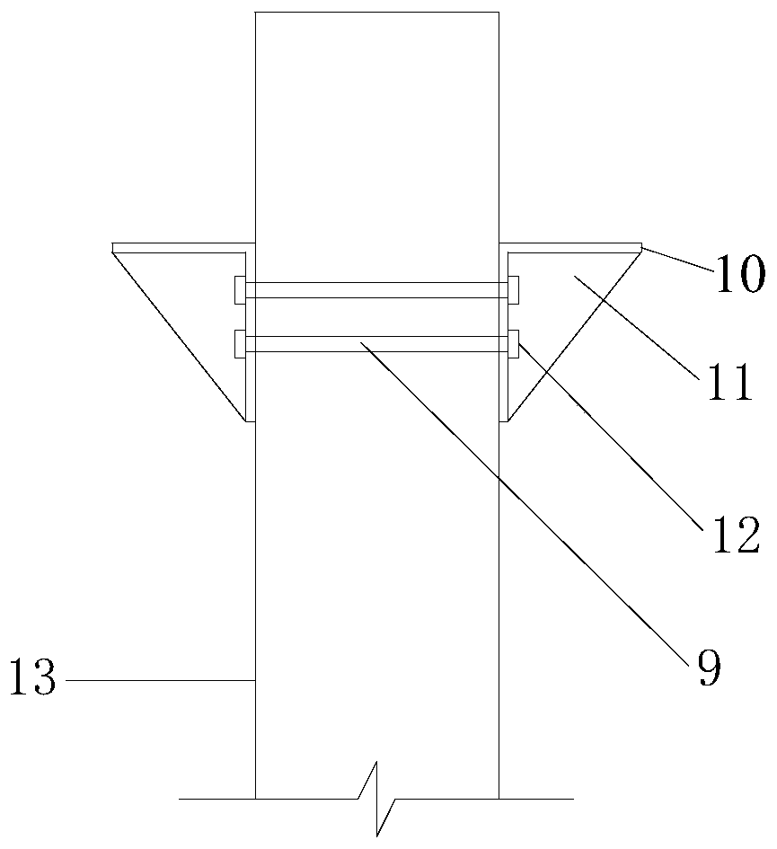
[0040] Such as figure 1 As shown, during the construction of the columnar high pier 13, two rows of through holes 9 are reserved at a suitable position on the upper part, and then an L-shaped hoop plate 10 is respectively arranged on both sides of the through hole 9, and the L-shaped hoop plate 10 Stiffeners 11 and two reserved bolt holes are arranged in the center, through two rows of through holes 9 and two bolt reserved holes, two pull bolts 12 are set to form...


PUM


Abstract

The invention relates to a cast-in-situ box girder support system. The cast-in-situ box girder support system comprises vertical column support, holt hoop iron support, electric hydraulic jacks, transverse beams, Bailey beams and a bottom mold beam. The vertical column support is mainly composed of two steel vertical columns and foundation. The electric hydraulic jacks are arranged on the steel vertical columns. A vertical column tie beam is arranged between the two steel vertical columns. The foundation is arranged in tip position of a high-order area of steep terrain. A high pier is arrangedin a low-order area of steep terrain. The holt hoop iron support is mainly composed of through holes, L-shape holt hoop iron plates, stiffening ribs and split bolts. The through holes are preformed in the high pier. The L-shape holt hoop iron plates are provided with bolt preformed holes and the stiffening ribs. The split bolts are arranged in the through holes and the bolt preformed holes. The cast-in-situ box girder support system has the beneficial effects that a holt hoop iron support system is formed by utilizing the existing high pier, the technology in the traditional technology that the steel vertical columns are erected beside the high pier is reduced, the construction speed is improved, and the project cost is lowered.

Description

technical field [0001] The invention relates to a support system, in particular to a cast-in-place box girder support system and a construction method thereof. Background technique [0002] At present, during the construction of cast-in-place beams, the general construction method is to first reinforce the foundation, and then set up a full support to place the formwork and steel bars and then carry out concrete pouring construction. A commonly used support form in the construction of cast-in-place box girders with high piers is the combined support of Bailey beams and steel pipe columns (that is, Bailey beams + steel pipe columns as supports), especially in the case of heavy loads, high pier columns, and large spans. , which is a more economical and safer bracket type. Related patents include: construction support system of cast-in-place box for high bridge piers (ZL 201520713361.0), a construction method for bridges with few supports, and bridges (ZL201610423219.1), const...

Claims


Application Information

Patent Timeline
Patent Type & Authority Applications(China)
IPC IPC(8): E01D21/00E01D2/04E01D101/24
CPCE01D21/00E01D2/04E01D2101/24
Inventor 齐昌广忻见敏王梁志张智超姜苏珂单艳玲
Owner NINGBO UNIV
Learn More