
Exhaustion aftertreatment system and method for regenerating a particle filter

一种废气后处理、颗粒过滤器的技术,应用在分散颗粒过滤、排气处理装置的电控、排气处理装置的诊断装置等方向,达到功率增加、大催化器容积、降低废气背压的效果

Active Publication Date: 2019-12-20
VOLKSWAGEN AG
View PDF6 Cites 4 Cited by
  • Summary
  • Abstract
  • Description
  • Claims
  • Application Information

AI Technical Summary

Problems solved by technology

[0005] However, these solutions have the disadvantage that, for the exothermic reaction, high temperature levels must already be reached in the exhaust system in order to convert the unburned exhaust gas components exothermically

Method used


Image

  • Exhaustion aftertreatment system and method for regenerating a particle filter
  • Exhaustion aftertreatment system and method for regenerating a particle filter
  • Exhaustion aftertreatment system and method for regenerating a particle filter

Examples


Embodiment Construction

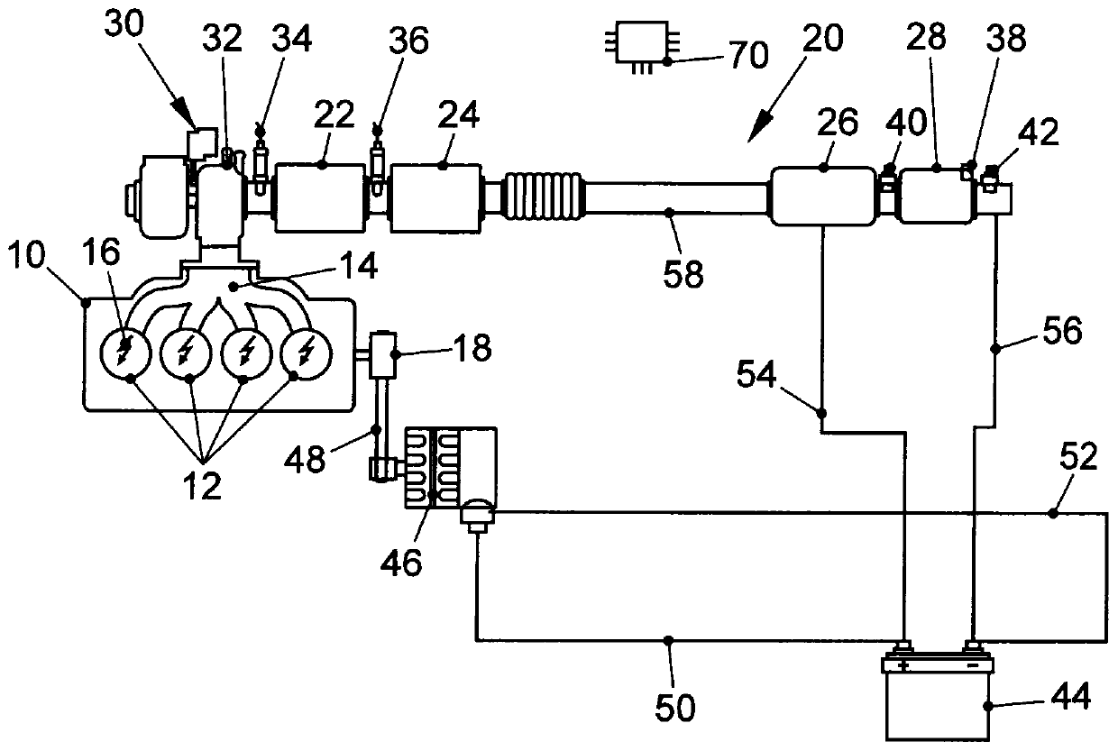
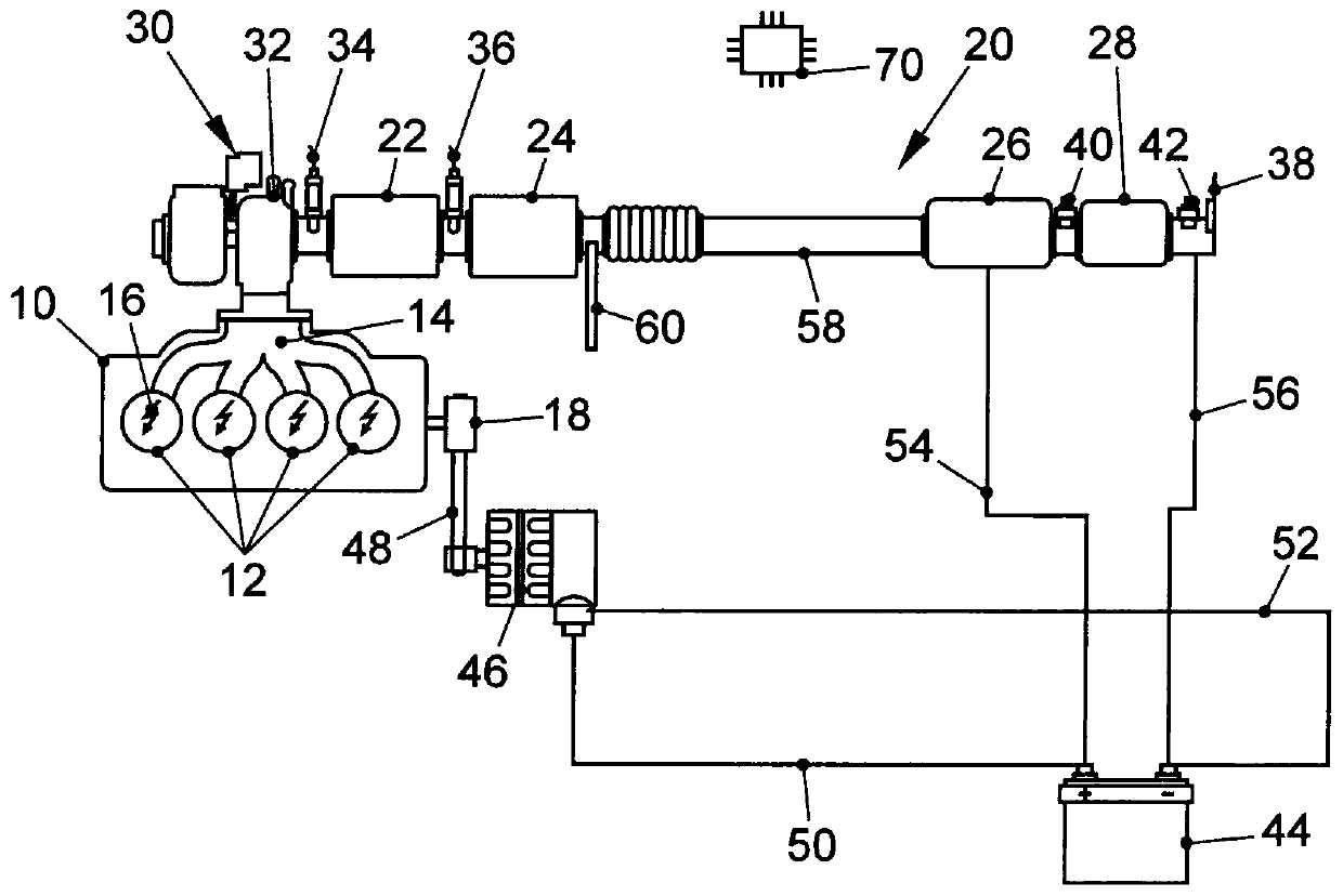
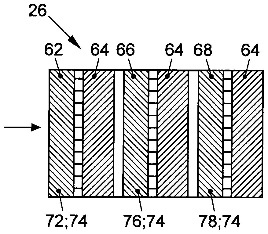
[0031] figure 1 Internal combustion engine 10 is shown with ignition from an external source by means of spark plugs 16 . The internal combustion engine has a plurality of combustion chambers 12 . Internal combustion engine 10 is connected via its exhaust port 14 to an exhaust system 20 . Furthermore, an output shaft 18 is provided on internal combustion engine 10 , which drives a generator 46 via a drive element 48 . The drive element 48 can in particular be designed as a belt or a chain. The exhaust device 20 includes an exhaust gas passage 58, in which the turbine 32 of the exhaust gas turbocharger 30 is arranged along the flow direction of the exhaust gas flowing through the exhaust gas passage 58, and the second turbine 32 of the exhaust gas turbocharger 30 is arranged downstream of the turbine 32 and is close to the three-way catalytic converter. A catalytic converter 22 and a further three-way catalytic converter 24 are arranged downstream of the first three-way cata...


PUM


Abstract

The invention relates to an exhaust aftertreatment system for an internal combustion engine (10). The exhaust aftertreatment system comprises an exhaust system (20) having at least one three-way catalyst (22, 24) near the engine, wherein a particulate filter (28) is arranged downstream from the three-way catalyst, preferably in an underbody installation in a motor vehicle. A heated catalyst (26),which has at least one heating stage (62, 66, 68) that can be heated by means of an electric heating element (72, 74, 76, 78), is provided upstream from the at least one three-way catalyst (22, 24) and downstream from the particulate filter (28). It is provided that the at least one electrically heatable heating stage (62, 66, 68) is supplied with electric power directly from a generator (46) thatis operatively connected to the internal combustion engine (10), so that heating of the heated catalyst (26) takes place essentially independently of the charge status of the vehicle battery (44). The invention also relates to a method for regeneration of a particulate filter (28) in the exhaust system (20) of an internal combustion engine (10) by means of such an exhaust aftertreatment system.

Description

technical field [0001] The invention relates to an exhaust gas aftertreatment system for an internal combustion engine and a method for regenerating a particle filter in an exhaust system of a gasoline engine. Background technique [0002] Increasingly stringent emission regulations place high demands on vehicle manufacturers, which are met by corresponding measures to reduce raw engine emissions and corresponding exhaust gas aftertreatment devices. With the introduction of the EU6 regulation, a limit value for the number of particles was set for petrol engines, which necessitated the use of a particle filter in many cases. Such soot particles are produced especially after a cold start of the internal combustion engine due to incomplete combustion resulting from a substoichiometric combustion air ratio after a cold start, cold cylinder walls and inhomogeneous mixing in the combustion chamber of the internal combustion engine gas distribution. Unlike the load on the diesel ...

Claims


Application Information

Patent Timeline
Patent Type & Authority Applications(China)
IPC IPC(8): F01N9/00F01N3/027F01N3/20F01N13/00
CPCF01N9/002F01N3/027F01N3/2013F01N13/009F01N13/0093F01N3/021F01N3/035F01N3/05F01N2240/16Y02A50/20Y02T10/12Y02T10/40B01D46/0027B01D53/9454B01D53/9477B01D2255/904B01D2279/30F01N3/023F01N3/101F01N3/30F01N11/007F01N2250/02F01N2430/06F01N2550/04F01N2560/025F01N2900/1402F01N2900/1602F01N2900/1606B01D46/84
Inventor S.帕克纳F-C.B.冯库梅恩-林登斯特杰纳M.曼兹
Owner VOLKSWAGEN AG
Learn More