

Spaceflight load vibration reducing box for rocket launching conditions
A technology of rocket launching and damping box, which is applied to the design features of spring/shock absorber, spring/shock absorber, and non-rotational vibration suppression. Vibration effect, vibration performance improvement, and the effect of reducing transient acceleration impact
Pending Publication Date: 2019-12-20
SHENYANG INST OF AUTOMATION - CHINESE ACAD OF SCI
View PDF0 Cites 4 Cited by
- Summary
- Abstract
- Description
- Claims
- Application Information
AI Technical Summary
Problems solved by technology
This complex vibration environment will cause the performance accuracy of the components in the microinj
Method used
View moreImage
Smart ImageViewing Examples

Examples
 PUM
| Property | Measurement | Unit |
|---|---|---|
| Density | aaaaa | aaaaa |
| Thickness | aaaaa | aaaaa |
Abstract
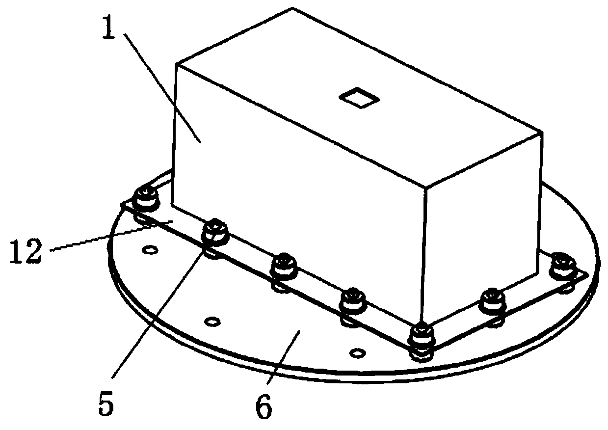
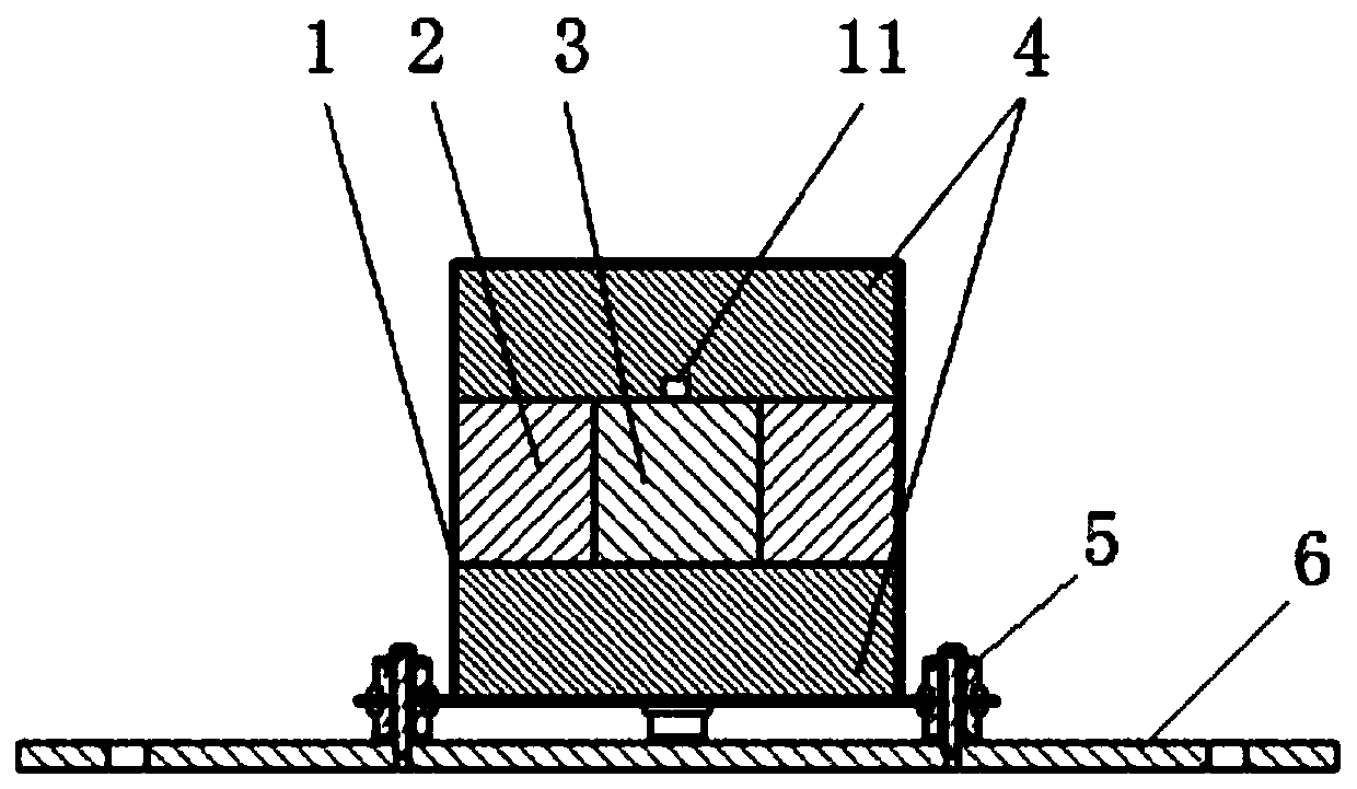
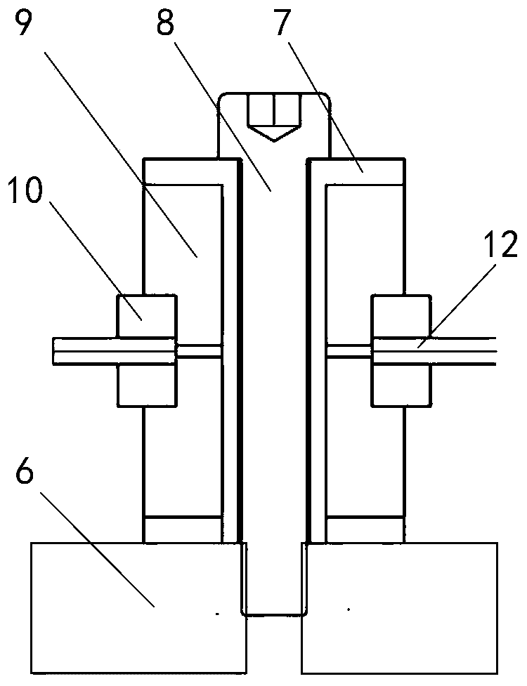
The invention belongs to the vibration control and vibration reducing technology field, and particularly relates to a spaceflight load vibration reducing box for rocket launching conditions. The spaceflight load vibration reducing box for the rocket launching conditions comprises a box body, a primary vibration reducing structure, a secondary vibration reducing structure, a macro manipulator, a box body mounting tool and an acceleration sensor, wherein the bottom of the box body is connected with the box body mounting tool through the primary vibration reducing structure, the macro manipulatoris arranged in the box body through the secondary vibration reducing structure, the first vibration reducing structure is used for reducing high frequency vibration response, the secondary vibrationreducing structure is used for reducing vibration of low frequency resonance response, and the acceleration sensor is arranged on the macro manipulator and used for acquiring vibration signals under the corresponding vibration conditions. The spaceflight load vibration reducing box for the rocket launching conditions can perform effective vibration reducing on a test instrument through the secondary passive vibration reducing technology, thereby effectively protecting the test instrument, and the design of the vibration reducing box and a test method thereof can provide reference to related fields, and play a critical part in vibration reducing protection of a space science load launching segment.
Description
technical field [0001] The invention belongs to the technical field of vibration control and vibration reduction, in particular to an aerospace load vibration reduction box used in rocket launch conditions. Background technique [0002] In the exploration of space life, the current research at home and abroad is mainly to study the survival of space cells through some bacteria and cell culture methods, but there is no report on the use of microinjection to intervene in the later development of cells and embryos. However, entering space after injection on the ground will be affected by factors such as the launch process. If the microinjection experiment can be carried out in the space environment, the introduction of other influencing factors such as the launch process can be eliminated, and the ground operation and the control experiment of the post-injection development process in the space microgravity environment can be carried out. It is of great significance to protect...
Claims
Login to View More Application Information
Patent Timeline
 IPC IPC(8): F16F15/02F16F15/08F16F3/093F16F3/087
CPCF16F3/0876F16F3/093F16F15/02F16F15/08F16F2230/08
Inventor骆海涛王浩楠刘广明于长帅富佳王昊辰
OwnerSHENYANG INST OF AUTOMATION - CHINESE ACAD OF SCI