Micro-adjustment method for coordinate position of equipment

A technology of micro-adjustment and equipment coordinates, which is applied in the direction of program control in control/regulation systems, instruments, sequence/logic controllers, etc., can solve problems such as limiting the scope of use, and achieve the effect of expanding the application range

Inactive Publication Date: 2019-12-20
XIAN AIRCRAFT IND GROUP
View PDF4 Cites 0 Cited by
  • Summary
  • Abstract
  • Description
  • Claims
  • Application Information

AI Technical Summary

Problems solved by technology

This limi

Method used


Image

  • Micro-adjustment method for coordinate position of equipment

Examples


Embodiment Construction

[0016] The principle of the present invention will be described below in conjunction with the accompanying drawings.

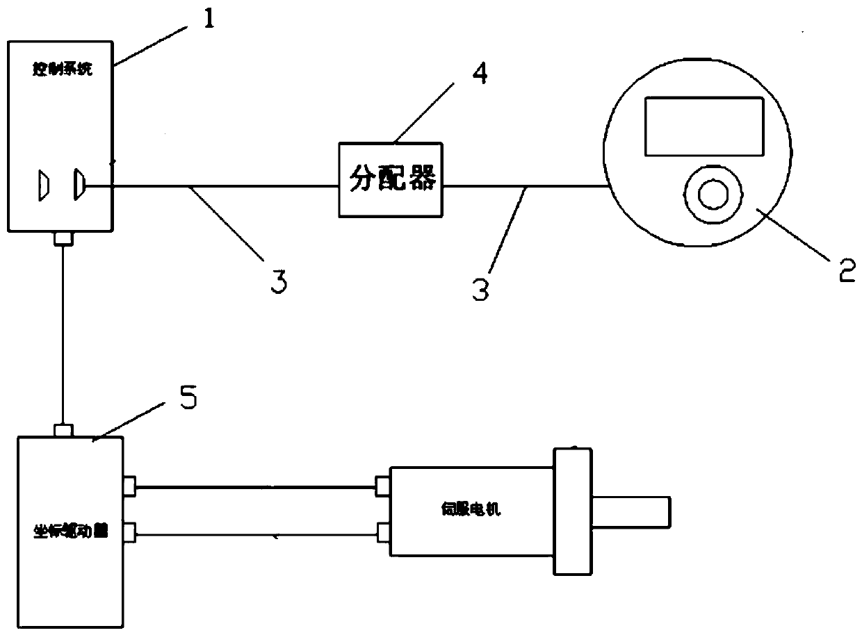
[0017] exist figure 1 Among them, a method for micro-adjustment of equipment coordinate position, including the following steps:

[0018] Step 1. Connect the hand-operated counter 2 with the machine tool control system 1. The signal of the hand-operated counter is transmitted to the distributor 4 through the PLC communication bus 3. After the distributor 4 shapes and recodes the signal, it is converted into a signal that is compatible with the control system. 1 to match the signal. .

[0019] Step 2: Add a coordinate position fine-tuning control subroutine in the PLC control main program.

[0020] Two independent variables are set in the coordinate position fine-tuning control subroutine to respectively record the number of grids that the hand counter 2 rotates in positive and negative directions. The positive and negative correspond to the moving direction...


PUM


Abstract

The invention discloses a micro-adjustment method for the coordinate position of equipment. The method comprises the following steps: connecting a hand counter with a machine tool control system; adding a coordinate position micro-adjustment control subprogram in a PLC (Programmable Logic Controller) control main program; inputting a coordinate position micro-adjustment amount by turning cells onthe hand counter; calculating the required moving displacement of a machine tool coordinate axis by the coordinate position micro-adjustment control subprogram according to the coordinate position micro-adjustment amount input on the hand counter; and inputting the displacement into a machine tool driver command register, and controlling the machine tool coordinate axis to move to a specified position.

Description

technical field [0001] The invention relates to the field of industrial automation control, in particular to a method for micro-adjustment of equipment coordinate positions. Background technique [0002] There are three ways to change the coordinate position of the equipment: ① program mode; ② manual mode; ③ micro-adjustment mode. The micro-adjustment method is mainly used in the precise positioning of the coordinate position of the equipment, for example, the alignment of the reference hole, the precise alignment of the installation hole, and so on. Compared with the other two methods, it has the advantages of flexible adjustment, quickness and high efficiency. At present, the familiar micro-adjustment device of equipment coordinate position is "manual pulse generator". In terms of hardware connection, it is connected to the special interface of "pulse generator" of the numerical control system through a special distributor. When the "manual pulse generator" is turned, it...

Claims


Application Information

Patent Timeline
IPC IPC(8): G05B19/05
CPCG05B19/054G05B2219/1129
Inventor 张耀词王高红席勇蔚腾孙银娟
Owner XIAN AIRCRAFT IND GROUP
Why Eureka
Try Eureka