A locking, unlocking, grabbing and lifting device for lead-based reactor fuel assemblies

A technology for lead-based reactors and fuel components, applied in the direction of reactor fuel elements, assembly of fuel elements, reactors, etc., can solve the problem of fuel assembly moving up and down, difficult to withstand the high temperature of liquid lead-bismuth coolant, high corrosion and high radiation environment seismic load synthesis Function and other issues, to achieve the effect of avoiding corrosion

Active Publication Date: 2020-07-14
INST OF MODERN PHYSICS CHINESE ACADEMY OF SCI
View PDF8 Cites 0 Cited by
  • Summary
  • Abstract
  • Description
  • Claims
  • Application Information

AI Technical Summary

Problems solved by technology

Although this locking mechanism takes advantage of the large buoyancy of the liquid lead-bismuth alloy, it does not realize the locking of the fuel assembly in the true sense, and the fuel assembly still has the possibility of moving up and down, especially in earthquake conditions. The fuel assembly moves up and down, causing the lock slider to slide to the unlocked position, causing the fuel assembly to be unlocked
[0007] As mentioned above, the existing fuel assemblies are difficult to withstand the combined effect of high temperature, high corrosion, high radiation environment in the reactor and seismic load of the liquid lead-bismuth coolant in the lead-based reactor

Method used


Image

  • A locking, unlocking, grabbing and lifting device for lead-based reactor fuel assemblies
  • A locking, unlocking, grabbing and lifting device for lead-based reactor fuel assemblies
  • A locking, unlocking, grabbing and lifting device for lead-based reactor fuel assemblies

Examples


Embodiment 1

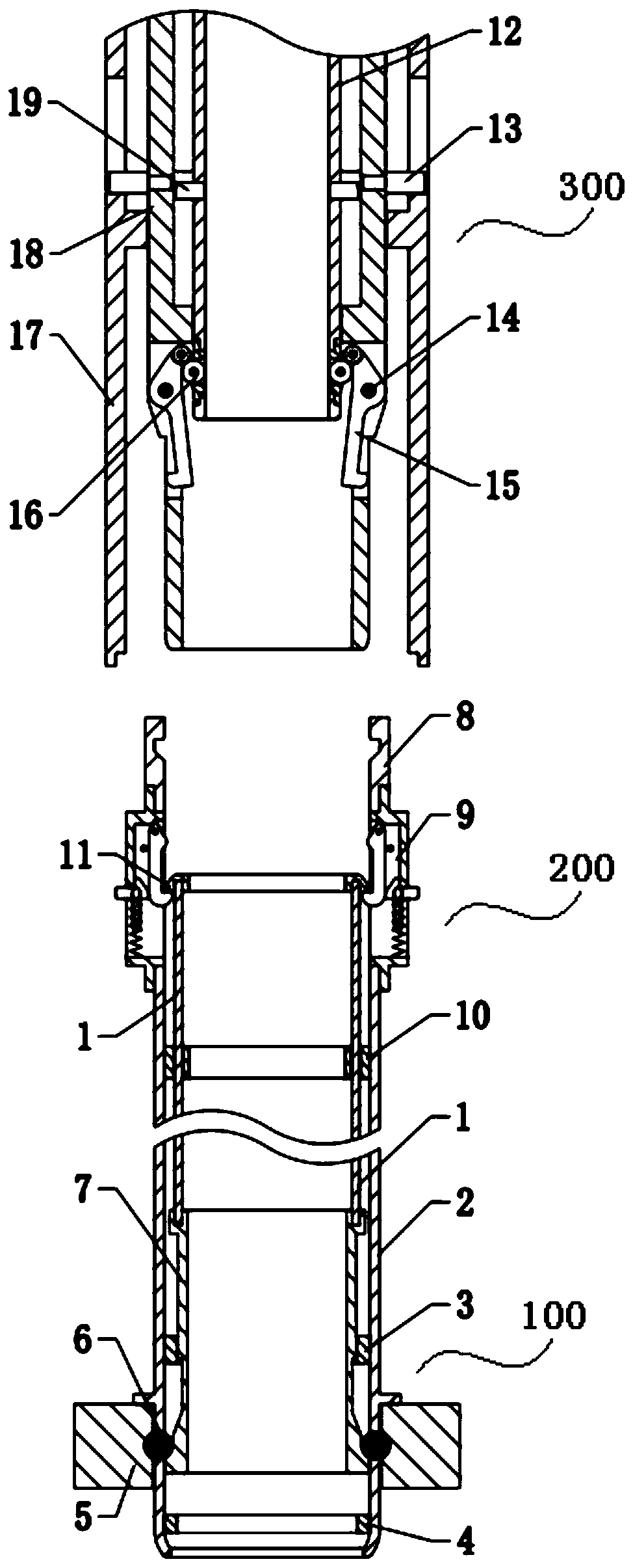
[0090] When feeding, it is necessary to unlock the spent fuel assembly from the core grid plate 5 and put out the lead-based reactor core (the state before feeding is as follows: Figure 21 shown), the steps include:

[0091] In the first step, the refueling head mechanism 300 moves to the top of the upper pipe seat self-locking mechanism 200, and the outer pusher 17 of the refueling head mechanism 300 moves downwards to meet the side ear 961 of the slider 96 in the hook box 91. Contact, make it overcome the buoyancy of spring 951 resistance and lead-based coolant, move down along guide pin 952, removed slide block 96 to the restraint that self-locking claw 93 rotates outwards around self-locking claw pin 92 ( The status is as Figure 22 shown);

[0092] In the second step, the middle push cylinder 18 of the refueling head mechanism 300 moves downward. First, the outer edge of the lower end of the middle push cylinder 18 will push the protrusion on the inner wall surface of ...

Embodiment 2

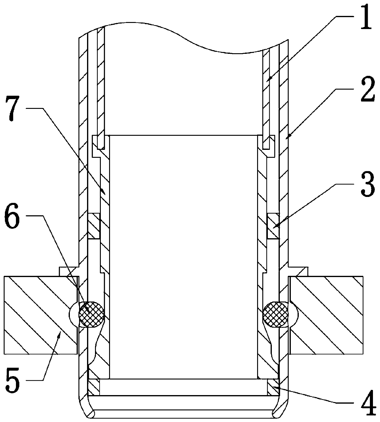
[0096] When charging, new fuel assemblies need to be placed in the core of the lead-based reactor. The fuel assembly moves down to the core grid plate 5 (this state is as Figure 26 shown), the steps include:

[0097] The first step is to insert the lower nozzle base 2 into the hole of the core grid plate 5, and after the limiting boss outside the lower tube base 2 contacts the core grid plate 5, the new fuel assembly moves vertically downward as a whole and is subject to pressure. Constraint, stop sinking (this state is as Figure 27 shown);

[0098] In the second step, the inner push cylinder 12 of the refueling head mechanism 300 is moved upwards, and the roller 161 of the roller box 16 is moved to the end arc surface of the inner wall surface of the locking claw 15, so that the locking claw 15 surrounds the locking claw Bearing pin 14 rotates to the inside, and now the connection between the locking hook 15 of the refueling head mechanism 300 and the upper pipe seat 8 i...


PUM


Abstract

The invention relates to a locking, unlocking and grabbing lifting device of a lead-based reactor fuel assembly. The device comprises a lower tube base buoyancy locking mechanism, an upper tube self-locking mechanism and a material changing gripper mechanism, wherein the lower tube base buoyancy locking mechanism pushes ball anchors out of a lower tube base through upward movement of a floating sliding barrel and embeds the ball anchors in locking grooves in a reactor grid plate, so that the ball anchors limit displacement of the lower tube base and the reactor grid plates in a stop pin manner, and the lower tube base is located on the reactor grid plate; the upper tube base self-locking mechanism is used for preventing the ball anchors from unlocking due to downward movement of the floating sliding barrel; and the material changing gripper mechanism is used for unlocking the lower tube base buoyancy locking mechanism and the upper tube self-locking mechanism and is also used for connecting an upper tube base lifting fuel assembly. Through mutual cooperation of three parts, the fuel assembly can be easily unlocked under the material lifting work condition, the fuel assembly is lifted to the outer side of a lead-based reactor core and is firmly locked on the reactor core grid plate under the work conditions of loading and operation.

Description

technical field [0001] The invention relates to a lead-based reactor assembly, in particular to a locking, unlocking, grasping and lifting device for a lead-based reactor fuel assembly. Background technique [0002] Lead-based reactor is a fast neutron reactor using molten lead or lead-bismuth alloy as coolant. It adopts a closed fuel cycle and can operate under normal pressure and high temperature conditions. Lead-based reactors have excellent fuel conversion capabilities, which can effectively increase the utilization rate of uranium and thorium resources, improve fuel sustainability, and can also be used to incinerate long-lived actinides in the spent fuel of existing light water reactors, so Clean use of nuclear energy. In addition, the inert and low-pressure coolant system in lead-based reactors further enhances reactor safety. [0003] The characteristics of lead and lead-bismuth alloys are: lead and lead-bismuth alloys are solid at room temperature, the melting poin...

Claims


Application Information

Patent Timeline
Patent Type & Authority Patents(China)
IPC IPC(8): G21C3/33G21C3/334G21C3/34
CPCG21C3/331G21C3/334G21C3/34Y02E30/30
Inventor 盛鑫顾龙于锐朱彦雷刘璐王大伟李金阳彭天骥张璐唐延泽秦长平范旭凯田旺盛姜韦李秀凌
Owner INST OF MODERN PHYSICS CHINESE ACADEMY OF SCI
Why Eureka
Try Eureka