Button switch automatic assembling machine convenient to rivet

An automatic assembly machine and riveting technology, applied in the field of mechanical equipment, can solve the problems of difficult to reliably guarantee the quality stability and consistency of button switches, high equipment cost and high labor intensity, etc. Connect clever effects

Inactive Publication Date: 2019-12-20
DONGGUAN UNIV OF TECH
View PDF3 Cites 2 Cited by
  • Summary
  • Abstract
  • Description
  • Claims
  • Application Information

AI Technical Summary

Problems solved by technology

[0006] The push button switch refers to the switch that uses the button to push the transmission mechanism to make the moving contact and the static contact press on or off and realize the circuit switching. The push button switch is a simple structure and widely used master electrical appliance. In the control circuit, it is used to manually send control signals to control contactors, relays, electromagnetic starters, etc. The button switch is generally composed of plastic parts, sealing rings, iron parts, riveting parts, screws, cover plates and protective covers, etc. The traditional The assembly of the button switch is mainly done manually. By manually assembling the parts together, the manual assembly method is not only labor-intensive and low in production efficiency, but also it is difficult to reliably guarantee the stability and consistency of the quality of the button switch produced. Some push-button switch assembly machines use assembly lines and manipulators for feeding the sealing rings and protective covers, which cost a lot of equipment and take up a lot of space. It is necessary to design a push-button switch assembly machine with clip-type feeding.

Method used


Image

  • Button switch automatic assembling machine convenient to rivet
  • Button switch automatic assembling machine convenient to rivet
  • Button switch automatic assembling machine convenient to rivet

Examples


Embodiment Construction

[0044] In order to enable those skilled in the art to better understand the technical solution of the present invention, the present invention will be described in detail below in conjunction with the accompanying drawings. The description in this part is only exemplary and explanatory, and should not have any limiting effect on the protection scope of the present invention. .

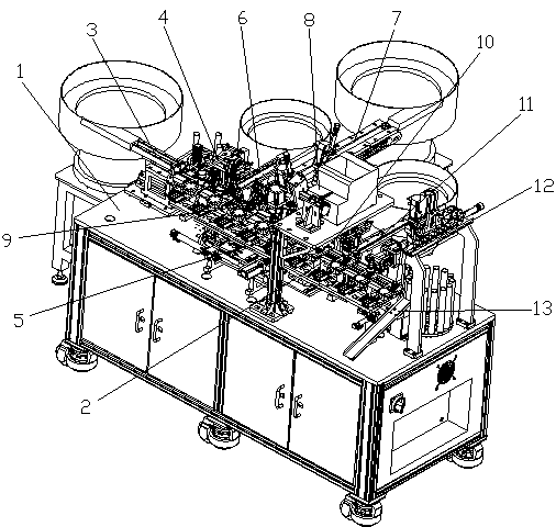
[0045] Such as Figure 1-Figure 14 As shown, the structure of the present invention is: a convenient riveting button switch automatic assembly machine, which includes a frame 1 and a power distribution control box arranged in the frame 1, and the middle part of the upper end of the frame 1 is provided with a main channel 2 , the starting end of the main channel 2 is connected to the plastic part feeding device 3, and the side is sequentially provided with a sealing ring transfer device 4, an iron part feeding device 6, a riveting part feeding device 7, and a riveting rotary Device 9, cover plate feedi...


PUM


Abstract

The invention relates to a button switch automatic assembling machine convenient to rivet. The button switch automatic assembling machine comprises a rack and a power distribution control box arrangedin the rack; a main runner is arranged in the middle of an upper end of the rack, a starting end of the main runner is connected with a plastic loading device; a sealing ring transfer device, an ironloading device, a riveting piece loading device, a riveting rotating device, a cover plate loading device and a protective cover loading device are orderly arranged at the side of the main runner from left to right, a tail end is connected with a blanking device, a screw locking device is arranged at an upper end, and a displacement module fixed on the rack is arranged below the screw locking device. The loading of multiple holders can be realized at once by driving the sealing ring loading rotatory table to rotate through a sealing ring rotary motor, the loading frequency and loading time are reduced, and the lifting of a sealing ring is realized by driving an optical axis through the cooperating of a sealing ring jacking cylinder and a linear slide rail module, the sealing ring sucker material taking is convenient, the loading way of enabling an assembly line to cooperate with a manipulator is substituted, and the cost input of the equipment is greatly reduced.

Description

[0001] Original application number: 2017111608194 [0002] Date of original filing: November 20, 2017 [0003] Applicant of the original case: Dongguan Institute of Technology [0004] Title of the original application: an automatic assembly machine for push button switches. technical field [0005] The invention relates to the field of mechanical equipment, in particular to a button switch automatic assembly machine convenient for riveting. Background technique [0006] Button switch refers to the switch that uses the button to push the transmission mechanism to make the moving contact and the static contact press on or off and realize the circuit switching. The button switch is a kind of master electrical appliance with simple structure and widely used. In the control circuit, it is used to manually send control signals to control contactors, relays, electromagnetic starters, etc. The button switch is generally composed of plastic parts, sealing rings, iron parts, riveti...

Claims


Application Information

Patent Timeline
Patent Type & Authority Applications(China)
IPC IPC(8): H01H11/00B23P21/00
CPCB23P21/00H01H11/00
Inventor 邓君廖梓龙
Owner DONGGUAN UNIV OF TECH
Why Eureka
Try Eureka