
Rapidly-installed photovoltaic module integrated board and installation method

A photovoltaic module and integrated board technology, applied in the field of solar photovoltaic power generation, can solve the problems of difficult operation of the mechanism, inconvenient movement and installation operation by workers, easy to get stuck, etc., so as to improve the efficiency of transportation and installation, and maximize the efficiency of photoelectric conversion. , the effect of improving the efficiency of the power station

Pending Publication Date: 2019-12-20
SHANGHAI JIAO TONG UNIV +1
View PDF1 Cites 2 Cited by
  • Summary
  • Abstract
  • Description
  • Claims
  • Application Information

AI Technical Summary

Problems solved by technology

However, subject to some objective conditions, there are many difficulties in increasing the size
The 72-piece module already weighs 50 catties, and its size has reached 2 meters high and 1 meter wide. It is inconvenient for workers to move and install
[0009] The driving force of the above-mentioned patent is to set the bottom of the photovoltaic module, which makes it difficult to start at the beginning of folding, especially when the photovoltaic panel is fully unfolded, the driving mechanism will easily get stuck due to the small initial force arm. or difficulties in the operation of the institution, etc.
Moreover, the structure of the above-mentioned patent is only a folding device for photovoltaic modules that are flat after being finally unfolded, and cannot realize folding for integrated boards of photovoltaic modules with curved surfaces.
Secondly, the structures of the above-mentioned patents do not include protective devices for photovoltaic modules during transportation and installation, nor do they consider structural design such as strengthening the connection stiffness between photovoltaic modules after deployment.

Method used


Image

  • Rapidly-installed photovoltaic module integrated board and installation method
  • Rapidly-installed photovoltaic module integrated board and installation method
  • Rapidly-installed photovoltaic module integrated board and installation method

Examples


Embodiment Construction

[0068] The present invention will be described in detail below in conjunction with specific embodiments. The following examples will help those skilled in the art to further understand the present invention, but do not limit the present invention in any form. It should be noted that those skilled in the art can make several modifications and improvements without departing from the concept of the present invention. These all belong to the protection scope of the present invention.

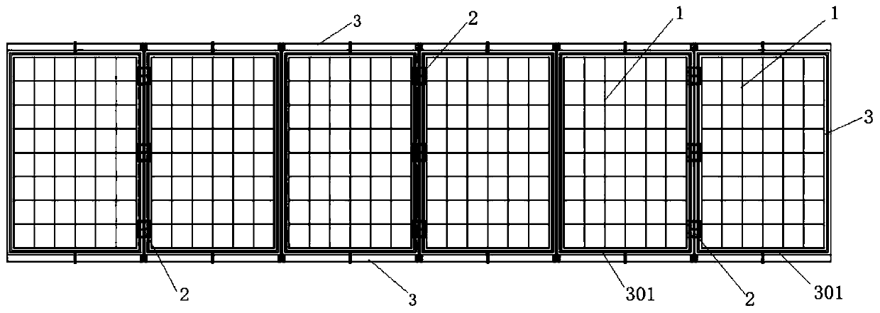
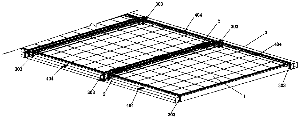
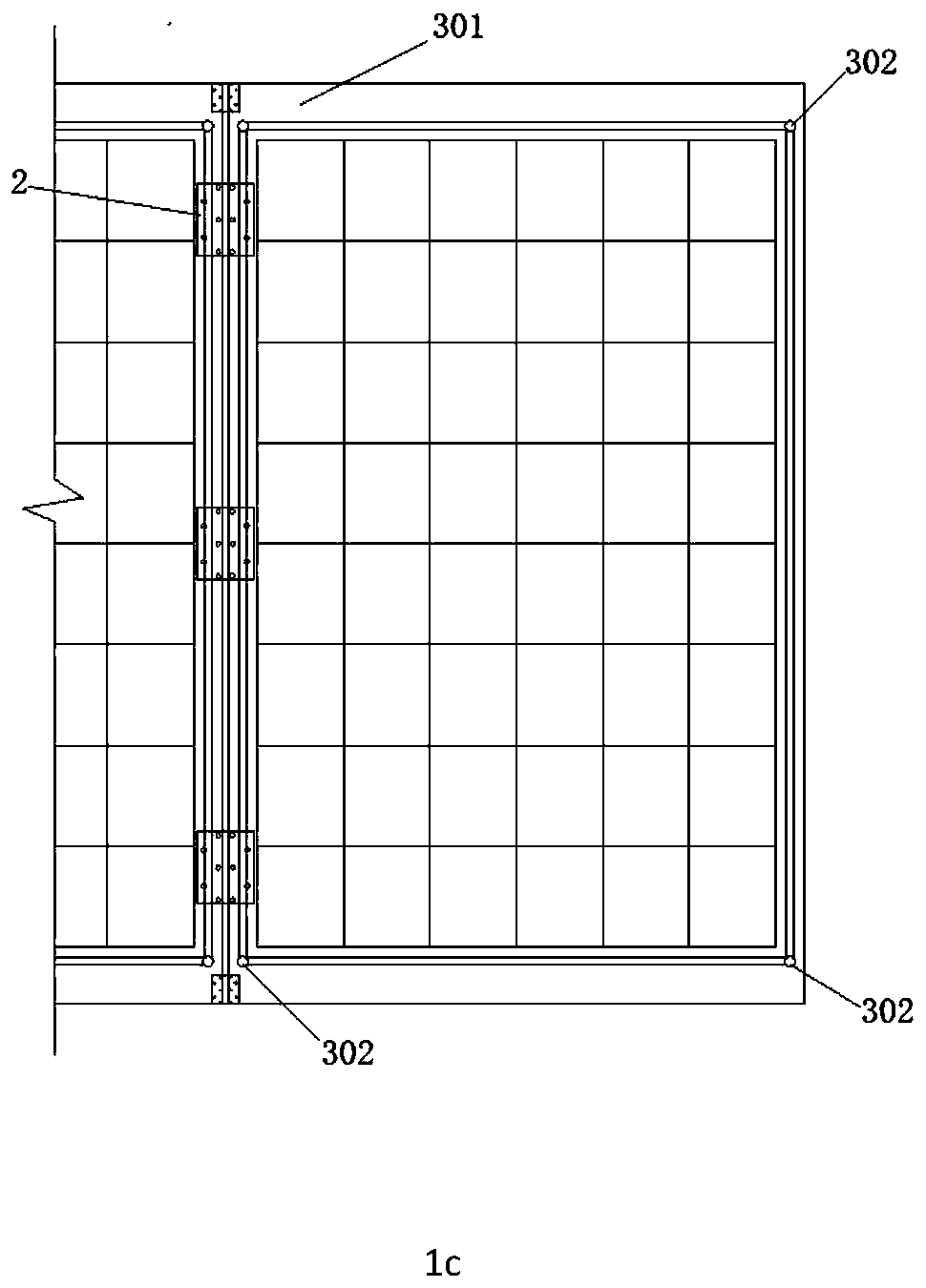
[0069] refer to Figure 1a , Figure 1b , Figure 1c , Figure 3b As shown, it is a schematic structural diagram of a photovoltaic module integrated board quickly installed according to an embodiment of the present invention, referring to Figure 3b As shown, the figure includes a plurality of photovoltaic module single boards 1 connected in series, a foldable integrated board fixing frame 3, and a positioning installation device 4, wherein the foldable integrated board fixing frame 3 includes a...


PUM


Abstract

The invention provides a rapidly-installed photovoltaic module integrated board and an installation method. The rapidly-installed photovoltaic module integrated board comprises a plurality of photovoltaic modules, a foldable integrated board fixing frame and a positioning installation device. The foldable integrated board fixing frame comprises a fixing frame component and a positioning hinge. Thepositioning installation device comprises at least two groups of positioning brackets and a driving part; the driving part drives the positioning brackets to move; a linkage mechanism is formed between the positioning brackets and the foldable integrated board fixing frame; and unfolding and folding of the foldable integrated board fixing frame are controlled through the positioning brackets. A plurality of photovoltaic module single boards connected in series are connected through a foldable integrated board fixing frame to form an integrated unit, the structural shape of the integrated unitafter being unfolded is controlled through the positioning angle of the positioning hinge, and the integrated unit is folded to form the size of one photovoltaic module single board or form a plane structure or a curved surface structure after being unfolded. Thus, a photovoltaic cell panel is protected, the transportation and installation efficiency is improved, and the construction cost of a photovoltaic power station is reduced.

Description

technical field [0001] The invention relates to solar photovoltaic power generation technology, in particular to a rapidly installed photovoltaic module integrated board and an installation method. Background technique [0002] The current traditional energy structure mainly includes fossil energy, such as coal, oil, natural gas, etc., which are produced through long-term chemical and biological reactions and are non-renewable. For the sustainable development of the energy structure of human society, new energy has become an inevitable choice. Solar energy has the advantages of being clean, inexhaustible, inexhaustible, renewable, and environmentally friendly. It is the most important and promising form of renewable energy and has broad development prospects. However, at present, the power generation of solar energy in the world is less than 0.1% of the total power generation, which is extremely disproportionate to the status of solar energy. The main reason is that the cos...

Claims


Application Information

Patent Timeline
IPC IPC(8): H02S30/10H02S30/20H02S20/30
CPCH02S30/10H02S30/20H02S20/30Y02E10/50
Inventor 王春江李建勇迟鸣声丁烨
Owner SHANGHAI JIAO TONG UNIV
Learn More