
Cold plate and cold plate manufacturing method

A manufacturing method and cold plate technology, which can be used in cooling/ventilation/heating transformation, electrical equipment construction parts, electrical components, etc., and can solve the problem of poor heat dissipation effect of cold plate

Active Publication Date: 2020-10-30
CHINA AVIATION OPTICAL-ELECTRICAL TECH CO LTD
View PDF8 Cites 0 Cited by
  • Summary
  • Abstract
  • Description
  • Claims
  • Application Information

AI Technical Summary

Problems solved by technology

[0003] The purpose of the present invention is to provide a cold plate to solve the problem of poor cooling effect of the cold plate in the prior art; in addition, the purpose of the present invention is to provide a cold plate manufacturing method

Method used


Image

  • Cold plate and cold plate manufacturing method
  • Cold plate and cold plate manufacturing method

Examples


Embodiment Construction

[0018] Embodiments of the present invention will be further described below in conjunction with the accompanying drawings.

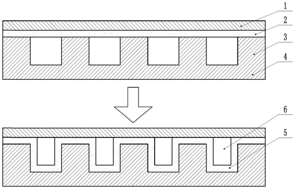
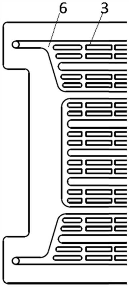
[0019] Specific embodiment 1 of the cold plate of the present invention, such as figure 1 and figure 2 As shown, the cold plate includes a cover plate 1, a bottom plate 4, and a brazing material layer 2 arranged between the cover plate 1 and the bottom plate 4 to weld the cover plate 1 and the bottom plate 4 together. The cooling channel 6, the bottom plate 4 is provided with a liquid inlet and a liquid outlet connected to the cooling channel 6, the cooling liquid flows into the cooling channel 6 from the liquid inlet, so that the heat generated by the bonding of the cooling liquid and the cover plate 1 The source performs heat exchange and then flows out from the liquid outlet, taking away the heat generated by the heat source to cool the heat source. After the brazing material layer 2 is melted, part of the brazing material layer 2 placed between th...


PUM


Abstract

The invention provides a cold plate and a method for manufacturing the cold plate. The cold plate includes a cover plate and a bottom plate welded together. The bottom plate is provided with at leastone cooling flow channel for a cooling liquid to flow. The cooling flow channel is provided therein with a roughened layer formed by a welding flux of the cover plate and the bottom plate melting andthen falling into the cooling flow channel. While the cover plate and the bottom plate are welded, a welding flux layer between the cooling flow channel and the cover plate is melted and then falls into the cooling flow channel to form the roughened layer in the cooling flow channel. After the cooling liquid flows into the cooling flow channel, bubbles in the cooling liquid are likely to be generated after the cooling liquid passes through the roughened layer. Thus, the cooling liquid can quickly take away heat, improve the heat transfer performance of the cold plate, and solve the poor heat dissipation of the cold plate in the prior art.

Description

technical field [0001] The invention relates to a cold plate and a method for manufacturing the cold plate. Background technique [0002] With the development of high-power and high-energy consumption equipment such as electronic equipment in various fields, liquid cooling and heat dissipation have also been deeply and widely used in this aspect. The structure of the traditional liquid-cooled cold plate is relatively simple. Through the bonding of the heating components and the liquid-cooled cold plate, the internal cooling medium circulates and conducts heat, and the heat conduction effect of the liquid-cooled plate is used to bring the heat of the components back to the liquid cooling source, thereby achieving heat dissipation. the goal of. When the heating power and heat flux density of equipment or components in the aviation field are high, the conventional cold plate structure design cannot meet the heat dissipation requirements, and a certain heat dissipation design f...

Claims


Application Information

Patent Timeline
Patent Type & Authority Patents(China)
IPC IPC(8): H05K7/20
CPCH05K7/20272
Inventor 朱腾飞田树王昆王扬坤
Owner CHINA AVIATION OPTICAL-ELECTRICAL TECH CO LTD
Learn More