
Buffering punch for punching die and punching method

A stamping die and punch technology, applied in the field of die, can solve the problems of high wear degree and unguaranteed quality of blanking parts, and achieve the effect of avoiding breaking punches and moving stably

Active Publication Date: 2019-12-24
RIZHAO CHAOJIE MASCH MFG CO LTD
View PDF6 Cites 10 Cited by
  • Summary
  • Abstract
  • Description
  • Claims
  • Application Information

AI Technical Summary

Problems solved by technology

[0004] In the actual stamping process, the most worn part of the entire die is undoubtedly the punch, so the punch with higher hardness is generally selected for stamping operations. In the repeated stamping process, due to the direct hard contact between the punch and the punched sheet, Sudden extreme stress will lead to a higher degree of wear
In addition, for blanking sheets of different thicknesses, the degree of wear on the punch is also different due to the different magnitudes of the punching force.
The worn punch needs to be replaced immediately, otherwise the quality of the processed blanking parts cannot be guaranteed

Method used


Image

  • Buffering punch for punching die and punching method
  • Buffering punch for punching die and punching method
  • Buffering punch for punching die and punching method

Examples


Embodiment Construction

[0021] The following will clearly and completely describe the technical solutions in the embodiments of the present invention with reference to the accompanying drawings in the embodiments of the present invention. Obviously, the described embodiments are only some, not all, embodiments of the present invention.

[0022] In describing the present invention, it should be understood that the terms "upper", "lower", "front", "rear", "left", "right", "top", "bottom", "inner", " The orientation or positional relationship indicated by "outside", etc. is based on the orientation or positional relationship shown in the drawings, and is only for the convenience of describing the present invention and simplifying the description, rather than indicating or implying that the referred device or element must have a specific orientation, so as to Specific orientation configurations and operations, therefore, are not to be construed as limitations on the invention.

[0023] refer to Figure ...


PUM


Abstract

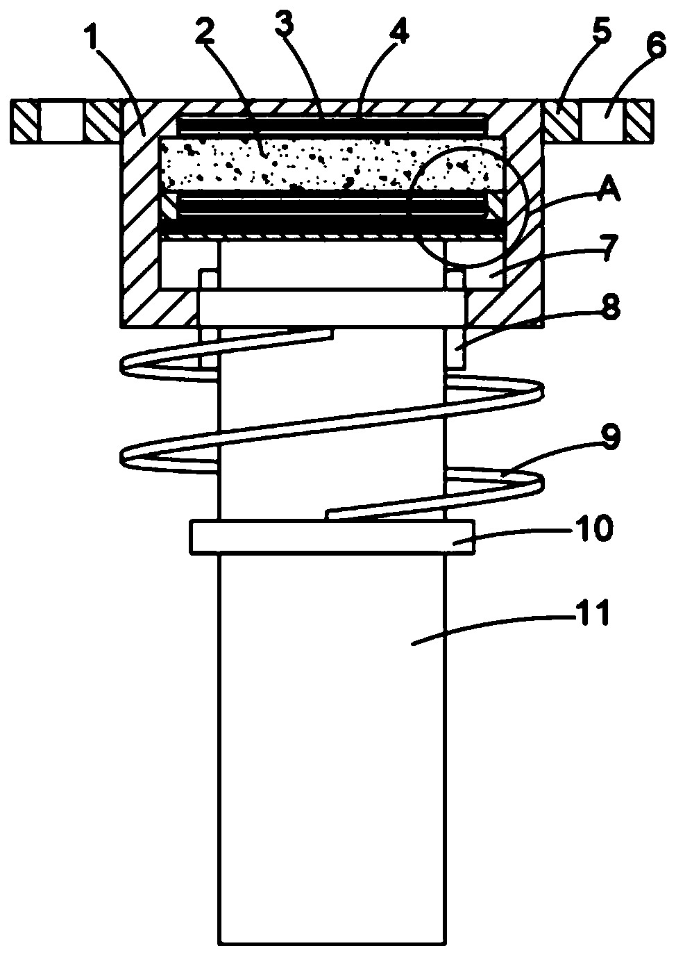
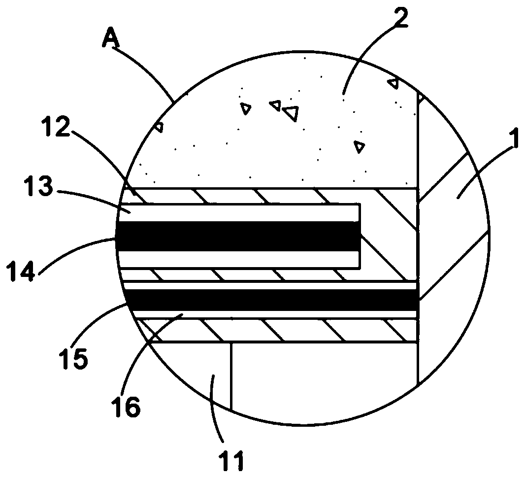
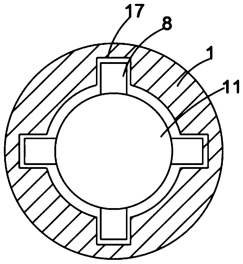
The invention discloses a buffering punch for a punching die and a punching method. The buffering punch comprises a mounting block, a mounting cavity is formed in the mounting block, a slide block isslidably connected to the interior of the mounting cavity, a vertical punch body is arranged on the side wall of the lower side of the slide block, and the side, away from the slide block, of the punch body penetrates through the side wall of the mounting block and is slidably connected with the side wall of the mounting block; a transverse first cavity is formed in the inner wall of the upper side of the mounting block, an upper capacitance plate is arranged in the first cavity, a transverse second cavity is formed in the slide block, and a lower capacitance plate parallel to the upper capacitance plate is arranged in the second cavity; a power port is formed in the side wall of one side of the mounting block, and electrically connected with the upper capacitance plate and the lower capacitance plate through a guide wire, and the portion between the inner wall of the upper side of the mounting block and the slide block is filled with electrorheological fluid. By means of the bufferingpunch for the punching die, the punch body can be sufficiently buffered, so that the punch body is prevented from being severely abraded, and thus the service life of the punch body is prolonged.

Description

[0001] This application is a divisional application with an application date of September 10, 2018 and an application number of CN201811048600.X, whose title is a buffer punch for stamping dies. technical field [0002] The invention relates to the technical field of dies, in particular to a buffer punch for a stamping die and a stamping method. Background technique [0003] Stamping die is a special process equipment for processing materials (metal or non-metal) into parts (or semi-finished products) in cold stamping processing, called cold stamping die (commonly known as cold stamping die). [0004] In the actual stamping process, the most worn part of the entire die is undoubtedly the punch, so the punch with higher hardness is generally selected for stamping operations. In the repeated stamping process, due to the direct hard contact between the punch and the punched sheet, Sudden extreme stress will lead to a higher degree of wear. In addition, for blanking sheets of d...

Claims


Application Information

Patent Timeline
Patent Type & Authority Applications(China)
IPC IPC(8): B21D28/14
CPCB21D28/14
Inventor 耿攀
Owner RIZHAO CHAOJIE MASCH MFG CO LTD
Learn More