
Dismountable motor for axle of electric vehicle

An electric vehicle, detachable technology, applied in the direction of the electric power device, axle, wheel, etc., can solve the problems of heavy workload, non-detachable motor, high energy efficiency ratio, etc., and achieve the effect of strong functionality, reasonable structure and easy disassembly

Pending Publication Date: 2019-12-24
LONGHAI TEV AUTOMOTIVE ELECTRONICS RES INST CO LTD
View PDF0 Cites 1 Cited by
  • Summary
  • Abstract
  • Description
  • Claims
  • Application Information

AI Technical Summary

Problems solved by technology

[0002] An electric vehicle refers to a vehicle that is driven by a vehicle-mounted power supply and driven by a motor to drive the wheels, and meets the requirements of road traffic and safety regulations. Devices, etc., due to their smaller impact on the environment than traditional cars, their prospects are widely optimistic, but the current technology is not yet mature, the working principle: battery - current - power regulator - motor - power transmission system - drive the car, as a clean energy The development of automobiles and electric vehicles has received extensive attention. Electric vehicles directly driven by axle motors are the most advanced driving method because they have no transmission system and high energy efficiency ratio;
[0003] In the prior art, this kind of electric vehicle also has a big defect, that is, because the axle motor is limited by the installation space, and the axle motor and the axle are mostly installed together, the motor cannot be disassembled, and the motor needs to be dismantled as a whole after it is damaged. The vehicle axle is overhauled, so the workload is relatively large, and it takes a lot of time and energy. For this reason, the present invention proposes a detachable electric axle motor

Method used


Image

  • Dismountable motor for axle of electric vehicle
  • Dismountable motor for axle of electric vehicle
  • Dismountable motor for axle of electric vehicle

Examples


Embodiment Construction

[0023] The following will clearly and completely describe the technical solutions in the embodiments of the present invention with reference to the accompanying drawings in the embodiments of the present invention. Obviously, the described embodiments are only some, not all, embodiments of the present invention. Based on the embodiments of the present invention, all other embodiments obtained by persons of ordinary skill in the art without making creative efforts belong to the protection scope of the present invention.

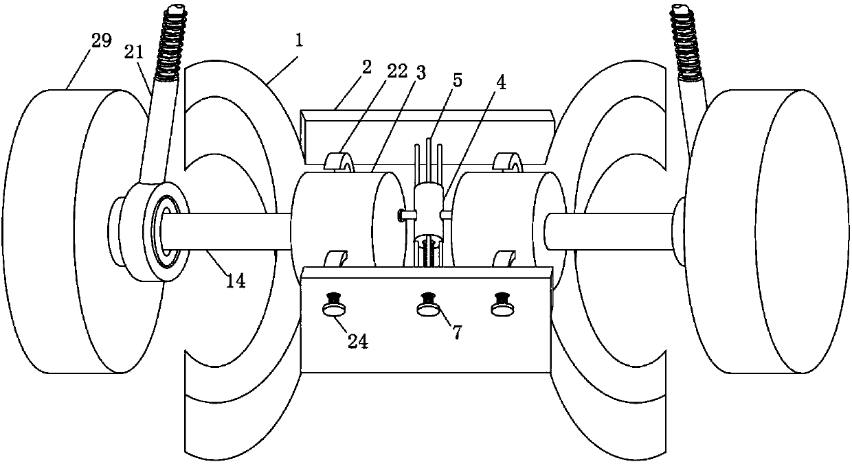
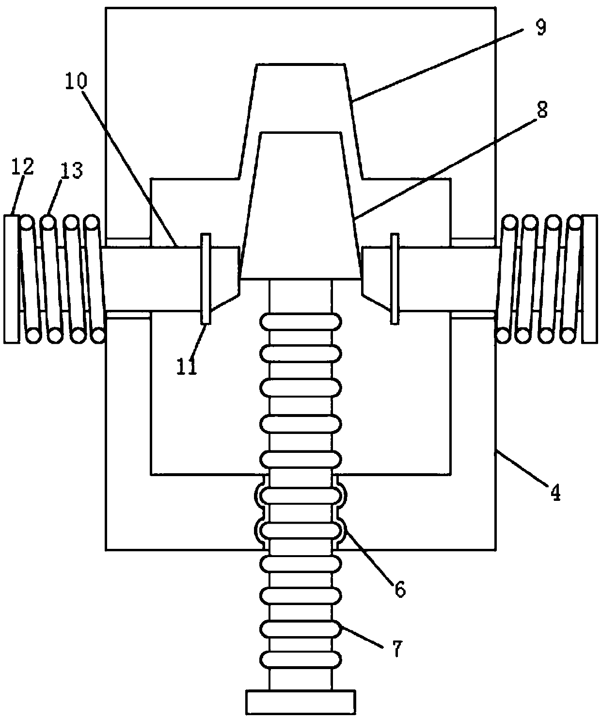
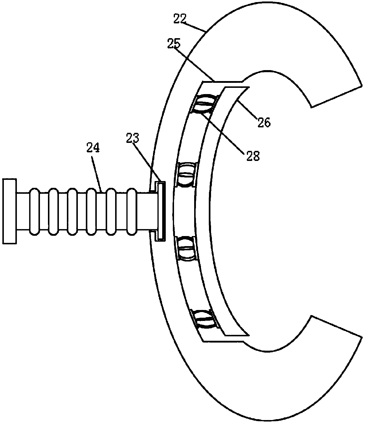
[0024] see Figure 1-7 , the present invention provides a technical solution: a detachable electric axle motor, including the axle frame body 1, the axle motor 3, the push cylinder body 4 and the clamping frame 22, the plate surface of the axle frame body 1 is welded with The enclosure plate 2, and the axle motor 3 is overlapped on the plate surface of the axle frame body 1, two axle motors 3 are provided, and a push cylinder 4 is arranged between the two axle...


PUM


Abstract

The invention discloses a dismountable motor for an axle of an electric vehicle. The dismountable motor comprises an axle frame, axle motors, a pushing barrel and clamping frames, wherein enclosing plates are welded on plate surfaces of the axle frame; the axle motors are supported on the plate surfaces of the axle frame; the number of the provided axle motors is two; the pushing barrel is arranged between the two axle motors; supporting cross bars are welded to the ends of the pushing barrel; the other ends of the supporting cross bars are welded to one surfaces of the enclosing plates; one end face of the pushing barrel is provided with a fastening screw hole; and a pushing screw rod is connected inside the fastening screw hole in a matching manner. The pushing barrel is arranged betweenthe two enclosing plates, and the pushing screw rod in the pushing barrel is screwed to withdraw a pushing block gradually from a positioning groove; while the pushing block is withdrawn, clamping bars on two sides of the pushing block gradually move into the pushing barrel under the elastic effects of first springs; and at the moment, for the axle motors, pushing forces towards docking barrels are missing, thereby facilitating the demounting of the axle motors.

Description

technical field [0001] The invention relates to the technical field of axle motors, in particular to a detachable electric axle motor. Background technique [0002] An electric vehicle refers to a vehicle that is driven by a vehicle-mounted power supply and driven by a motor to drive the wheels, and meets the requirements of road traffic and safety regulations. Devices, etc., due to their smaller impact on the environment than traditional cars, their prospects are widely optimistic, but the current technology is not yet mature, the working principle: battery - current - power regulator - motor - power transmission system - drive the car, as a clean energy The development of automobiles and electric vehicles has received extensive attention. Electric vehicles directly driven by axle motors are the most advanced driving method because they have no transmission system and high energy efficiency ratio; [0003] In the prior art, this kind of electric vehicle also has a big defe...

Claims


Application Information

Patent Timeline
IPC IPC(8): B60K1/02B60B35/12
CPCB60B35/12B60K1/02
Inventor 李秋宴肖奇斌王宝金杨国强吴锦涛欧阳璞陆光亮蔡来勋符小军陈少棠
Owner LONGHAI TEV AUTOMOTIVE ELECTRONICS RES INST CO LTD
Learn More