Automatic moving conveyor

A conveyor, self-moving technology, applied in the direction of conveyor objects, transportation and packaging, support frame, etc., can solve the problems of difficult and fast sorting things, inconvenience, complexity, etc., to improve the overall conveying efficiency, reduce manual handling or mechanical The effect of grasping, easy installation and movement

Pending Publication Date: 2019-12-24
广东友力智能科技有限公司
View PDF0 Cites 0 Cited by
  • Summary
  • Abstract
  • Description
  • Claims
  • Application Information

AI Technical Summary

Problems solved by technology

[0004] There are often multiple independent parallel conveying production lines in many processing workshops. The materials on the conveying production lines cannot be directly transferred to each other. The sorting position of each logistics belt needs to be equipped with multiple inspection devices, using push plates or other sorting mechanisms to realize the sorting function from a single conveyor belt to multiple conveyor belts. It is difficult for the push plate sorting mechanism to quickly sort things, and for the cross transfer of multiple production lines, a more complicated sorting supporting mechanism and real-time analysis system are required. Therefore, in response to these problems, we need a method that can realize multiple Conveyor unit for cross transfer of conveyor lines

Method used


Image

  • Automatic moving conveyor
  • Automatic moving conveyor
  • Automatic moving conveyor

Examples


Embodiment 1

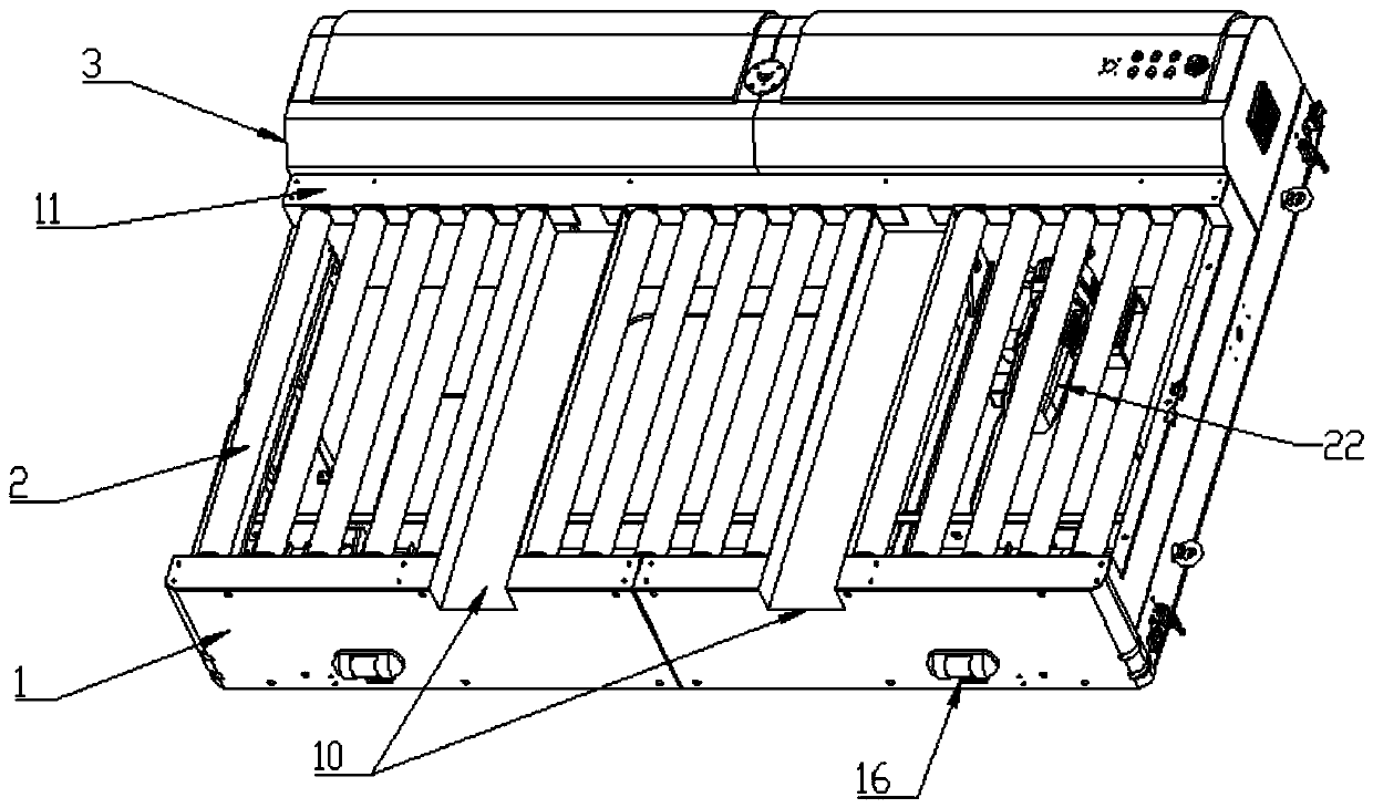
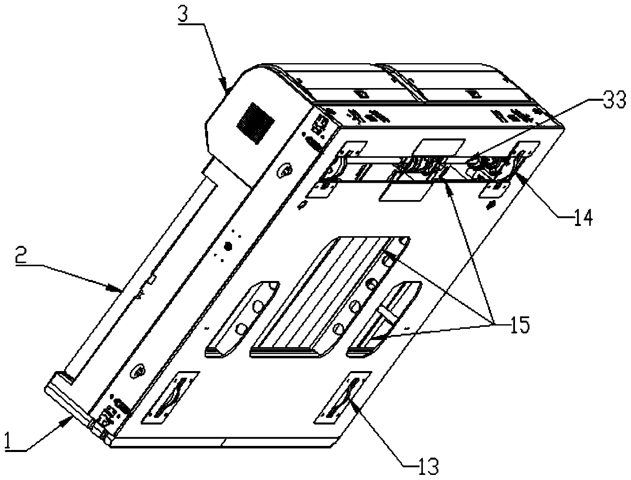
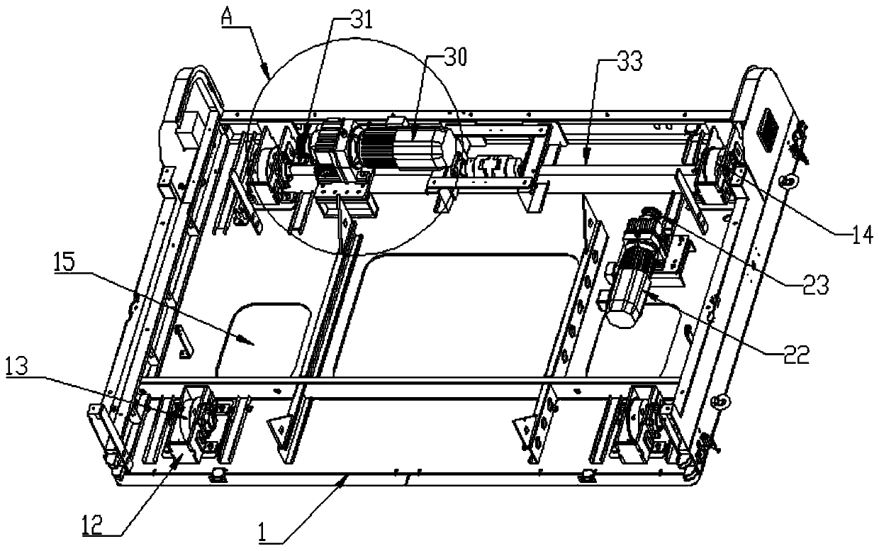
[0025] see Figure 1~4 , in an embodiment of the present invention, a self-moving conveyor includes a conveyor base 1, a row of conveying rollers 2 is fixed on the top surface of the conveyor base 1, and a roller motor is provided directly below the conveying rollers 2 22. The roller motor 22 drives the conveying roller 2 to roll on the surface of the conveyor base 1 through the roller driving mechanism. The conveying roller 2 is provided with a plurality of fork slots 10 for inserting fork plates at intervals. The conveyor base 1 The four corners of the bottom are provided with a plurality of wheels for driving the conveyor base 1 to move perpendicularly to the conveying direction of the conveying roller 2. The rear panel side of the conveyor base 1 is provided with a stroke motor box 3, and the stroke motor box 3 is equipped with There is a stroke drive mechanism that drives the wheels to rotate.

[0026] The roller driving mechanism includes a chain chamber 11 arranged at ...

Embodiment 2

[0031] The difference between this embodiment and embodiment 1 is:

[0032] The stroke drive mechanism and the roller drive mechanism are provided with a reduction device, and the reduction device includes a reduction gear box 34 .

[0033] The bottom surface of the conveyor base 1 is provided with an inspection opening 15 for maintenance, and the side wall of the conveyor base 1 is provided with a working indicator light 16 .

[0034] Working principle of the present invention: the reduction gear box 34 provided is used to reduce the speed of the stroke drive mechanism and the roller drive mechanism to increase the torque, the provided inspection port 15 is convenient for maintenance of the internal components of the conveyor base 1, and the provided working indicator light 16 It is mainly used to remind and warn the operator during the longitudinal movement of the conveyor base 1.


PUM


Abstract

The invention discloses an automatic moving conveyor. The conveyer comprises a conveyor base, wherein the top surface of the conveyor base is rotationally fixed with a row of conveying rollers, a roller motor is arranged right below the conveying rollers, the roller motor drives the conveying rollers to roll on the surface of the conveyor base through a roller driving mechanism, a plurality of fork position grooves for insertion of fork plates are arranged on the conveying rollers at intervals, a plurality of wheels used for driving the conveyor base to move in the direction perpendicular to the conveying direction of the conveying rollers are arranged at the four corners of the bottom of the conveyor base, a stroke motor box is arranged on one side of a rear panel of the conveyor base, and a stroke driving mechanism for driving the wheels to rotate is arranged in the stroke motor box. According to the conveyer, the whole conveyor base can be used as an object moving and carrying device to carry materials, the installation and the movement of the base are facilitated, and the cross conveying function can be realized by combining and matching with other conveying belts.

Description

technical field [0001] The invention specifically relates to a material transmission device, in particular to a self-moving conveyor. Background technique [0002] Conveyor is a common device for conveying materials. Most of the common conveyors on the market are belt conveyors or roller conveyors. Generally, the conveyor has a built-in motor, and the rotation of the belt or roller is realized by driving the belt or roller shaft through the motor. , so as to realize the transfer and transportation of materials. [0003] The general conveyors are mostly directly supported by brackets or installed on the ground. The conveyors on the production line are mostly combined, and the relative positions of multiple conveyors will be fixed according to the distribution of the production process. Therefore, the general conveyor is installed or installed. The use links are all fixed devices, which lack the flexibility of movement. [0004] There are often multiple independent parallel ...

Claims


Application Information

Patent Timeline
Patent Type & Authority Applications(China)
IPC IPC(8): B65G13/12B65G13/11B65G13/07B65G41/00B65G47/68
CPCB65G13/07B65G13/11B65G13/12B65G41/00B65G47/68
Inventor 刘扬珍梁程添
Owner 广东友力智能科技有限公司
Why Eureka
Try Eureka