Steam turbine for cracking gas device and cracking gas system

A pyrolysis gas, steam turbine technology, applied in mechanical equipment, engine components, machines/engines, etc., can solve problems such as safety accidents, difficulty in steam turbine alignment, and friction between moving and static parts

Pending Publication Date: 2019-12-24
HANGZHOU STEAM TURBINE
View PDF0 Cites 2 Cited by
  • Summary
  • Abstract
  • Description
  • Claims
  • Application Information

AI Technical Summary

Problems solved by technology

[0006] In view of this, the present application provides a steam turbine and a cracked gas system for a cracked gas device, the purpose of which is to solve to a certain extent the gap between the rotor and the bearing seat caused by the axial expansion of the high temperature steam inlet side of the steam turbine in the prior art. The relative position changes greatly, which reduces the technical problem of rotor rotation reliability
[0007] This application also solves to a certain extent the technical problems in the prior art that the lateral deflection produced by the steam turbine makes the centering of the steam turbine difficult, and friction between moving and static parts occurs, resulting in safety accidents
[0008] This application also solves to a certain extent the technical problem that the rotor system of the steam turbine in the prior art is difficult to meet the vibration assessment standard and does not have the ability to resist interference

Method used


Image

  • Steam turbine for cracking gas device and cracking gas system
  • Steam turbine for cracking gas device and cracking gas system
  • Steam turbine for cracking gas device and cracking gas system

Examples


Embodiment Construction

[0051] The technical solutions of the present application will be clearly and completely described below in conjunction with the accompanying drawings. Apparently, the described embodiments are some of the embodiments of the present application, not all of them. Based on the embodiments in this application, all other embodiments obtained by persons of ordinary skill in the art without making creative efforts belong to the scope of protection of this application.

[0052] In the description of this application, it should be noted that the terms "center", "upper", "lower", "left", "right", "vertical", "horizontal", "inner", "outer" etc. The indicated orientation or positional relationship is based on the orientation or positional relationship shown in the drawings, and is only for the convenience of describing the present application and simplifying the description, rather than indicating or implying that the referred device or element must have a specific orientation, use a spec...


PUM


Abstract

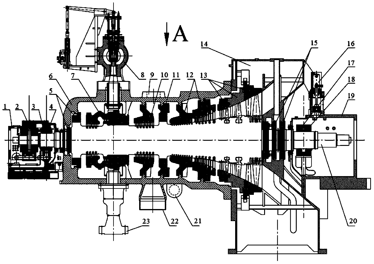
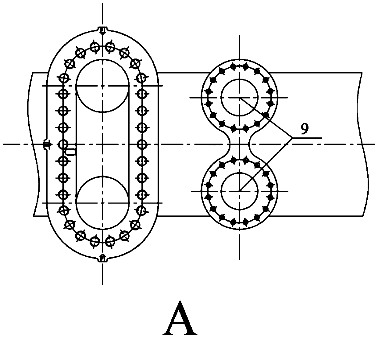
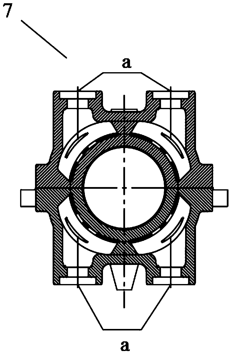
The invention provides a steam turbine for a cracking gas device and a cracking gas system, and relates to the technical field of steam turbines. The overall structure adopts a single-cylinder single-steam-exhaust arrangement, and a rotor system is supported through transverse bearings of various models and sizes, so that it is guaranteed that the system has a sufficient avoidance interval, excellent vibration performance and excellent anti-interference performance. The full-arc steam admission structure is adopted, the steam admission flow channel is optimized, the structural strength and rigidity are improved, a backflow structure is designed for through flow, and the axial thrust of the steam turbine is effectively lowered; a high-temperature side guiding structure is adopted, cold andhot state clearance change caused under a high-temperature running environment and a working condition emergence condition can be prevented, and the centring problem of steam cylinders of the steam turbine is solved; a detachable split valve-adjusting quick-closing valve structure is adopted, and the installing and overhauling mode is simplified; through the mode of multi-point supporting, the rigidity and heat stability of the steam exhaust cylinder are optimized, therefore, the industrial steam turbine with the power per unit of 100 MW can drive compressor units with the annual output of 1.5million tons of ethylene cracking gas, and the requirements of the compressor units for the working conditions and rotation speed change are met.

Description

technical field [0001] The present application relates to the technical field of steam turbines, in particular to a steam turbine and a cracked gas system for a cracked gas device. Background technique [0002] In the cracked gas system in the prior art, the deformation of the hot and cold state of the steam turbine is relatively large under variable load conditions and when starting and stopping, especially the axial expansion and lateral deflection generated on the high-temperature steam inlet side, wherein the axial expansion makes the main cylinder and The relative position between the bearing seats changes greatly, which reduces the reliability of the rotor rotation; and the lateral deflection will make the alignment of the steam turbine difficult, and friction between moving and static parts will occur, resulting in safety accidents; [0003] In the prior art, the operating speed range of the steam turbine rotor driving the compressor project is usually 70% to 105% of ...

Claims


Application Information

Patent Timeline
Patent Type & Authority Applications(China)
IPC IPC(8): F01D17/14F01D15/00F01D9/04F01D25/00F01D25/16F01D25/28
CPCF01D9/041F01D15/00F01D17/145F01D25/00F01D25/16F01D25/28
Inventor 孔建强毛汉忠张科马晓飞杨雄民李宏福陈金铨周立明胡海良陆晋张超赵海维王红梅刘白兰黄华安
Owner HANGZHOU STEAM TURBINE
Why Eureka
Try Eureka