Lamp for textile workshop

A technology for lamps and workshops, applied in cleaning methods and utensils, lampshades, lighting applications, etc., can solve the problems of weakening lighting effects, reducing production efficiency, reducing the brightness of bulbs, etc., to avoid dust accumulation, ensure stability, and prolong service life Effect

Active Publication Date: 2019-12-24
浏阳市恒信包装印刷有限公司
View PDF12 Cites 13 Cited by
  • Summary
  • Abstract
  • Description
  • Claims
  • Application Information

AI Technical Summary

Problems solved by technology

[0003] At present, when the dust on the lamps in the textile workshop is cleaned, they are cleaned with a rag on the surface of the lamps, and the lamps used in the textile workshop are large and fixed at a high position, resulting in uncertain cleaning time for the lamps, resulting in It will absorb a lot of dust, which will affect the lighting effect of the bulb. In addition, a large amount of dust adsorbed on the surface of the lamp will affect the heat dissipation effect of the lamp, which will cause a large amount of heat inside the bulb when it is illuminated, affecting the service life of the bulb. In addition, because there is a lot of floating dust in the textile workshop, the dust in the workshop is usually settled by sprinkling water, which makes the moisture in the textile workshop relatively large, so that the floating moisture in the textile workshop is easy to be absorbed by the light bulb. The surface of the lens liquefies to form a layer of water droplets. The existence of these water droplets will reduce the brightness of the bulb itself and weaken the lighting effect, thereby affecting the observation of the fabric surface by the producer, making it difficult for the producer to control the surface quality of the textile fabric well. , reducing production efficiency

Method used


Image

  • Lamp for textile workshop
  • Lamp for textile workshop
  • Lamp for textile workshop

Examples


Embodiment Construction

[0027] In order to make the above objects, features and advantages of the present invention more comprehensible, specific implementations of the present invention will be described in detail below in conjunction with the accompanying drawings. In the following description, numerous specific details are set forth in order to provide a thorough understanding of the present invention. However, the present invention can be implemented in many other ways different from those described here, and those skilled in the art can make similar improvements without departing from the connotation of the present invention, so the present invention is not limited by the specific implementations disclosed below.

[0028] It should be noted that when an element is referred to as being “fixed” to another element, it can be directly on the other element or there can also be an intervening element. When an element is referred to as being "connected to" another element, it can be directly connected ...


PUM


Abstract

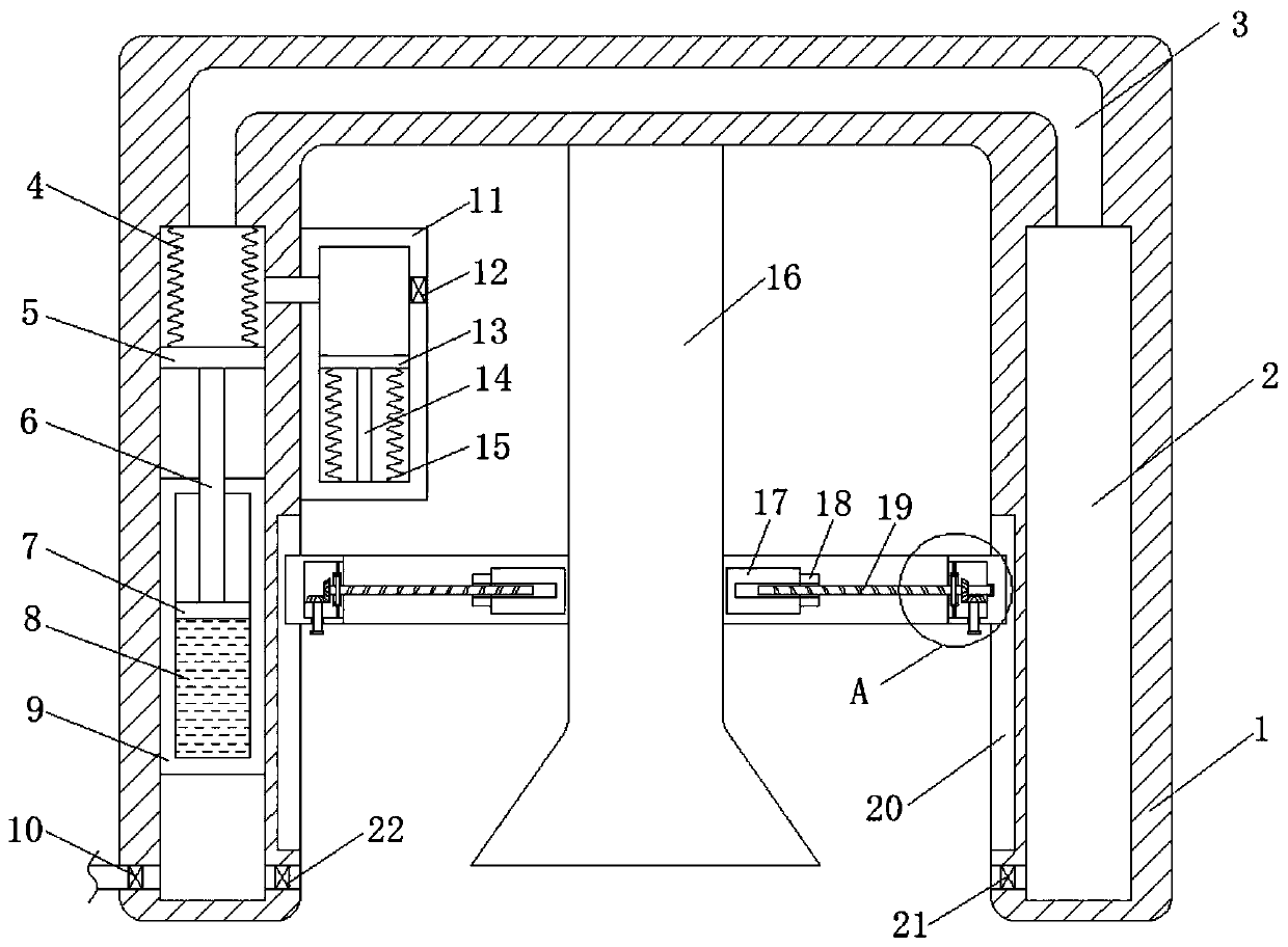
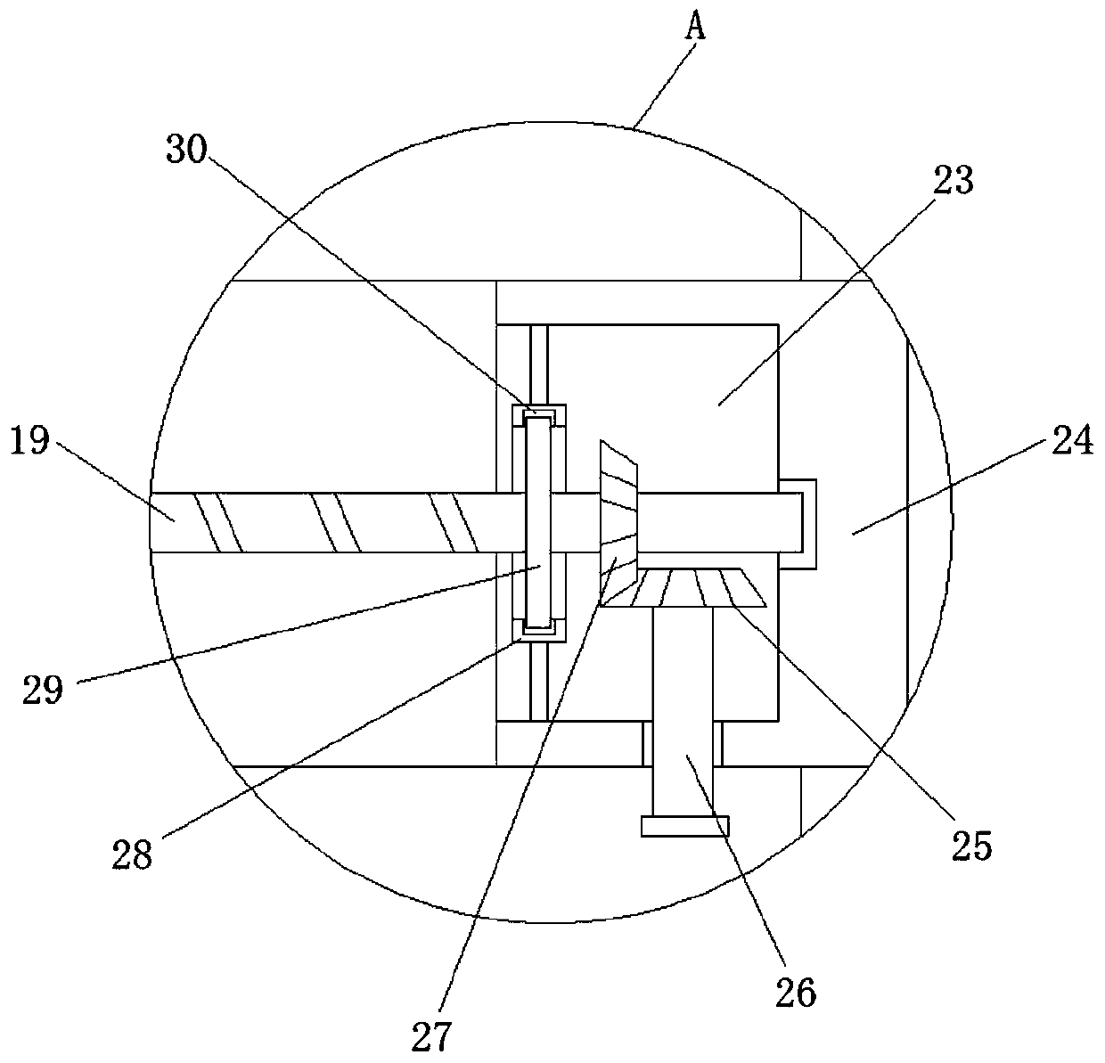
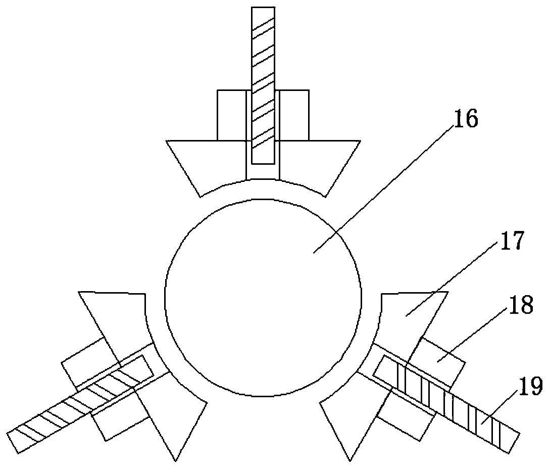
The invention discloses a lamp for a textile workshop. The lamp for the textile workshop comprises a lampshade and a bulb connected to the inner top of the lampshade in a threaded manner. Two first gas cavities are formed in the opposite side walls of the lampshade. The inner wall of the lampshade is provided with a first annular groove. The first gas cavities are internally provided with a drivedevice for cleaning the surface of the bulb. A fixing device for mounting and fixing the bulb is arranged in the first annular groove. Low-boiling point evaporation liquid in a liquid storage cylindergenerates steam when being heated, a second piston is made to move upward, a first piston is made to move upward, so that the inside of the first gas cavity on the left side is at the negative pressure, the inside of the first gas cavity on the right side is at the positive pressure, a first one-way valve and a second one-way valve are opened at the same time, dust on the bulb is cleaned and recycled, a bimetal sheet in a heat absorption box is heated and bent to enable a third piston to move downwards, so that hot gas in the lampshade is sucked d into the heat absorption box, hot gas is discharged through the first one-way valve of the first gas cavity communicating with the heat absorption box, and moisture on the bulb is evaporated.

Description

technical field [0001] The invention relates to the field of production lamps, in particular to a lamp for textile workshops. Background technique [0002] Lamps refer to appliances that can transmit light, distribute and change the light distribution of the light source, including all parts required to fix and protect the light source except the light source, as well as the necessary line accessories for connection to the power supply. Modern lamps include home lighting. , commercial lighting, industrial lighting, road lighting, landscape lighting and special lighting, etc., as a daily consumable in the lighting industry, with the progress of my country's economy and society, the emergence of new light sources such as fluorescent lamps, energy-saving lamps, and LEDs has led to the emergence of lighting fixtures. The earth-shaking evolution, among them, the light source of industrial lighting is mainly gas discharge lamps and fluorescent lamps, combined with other lamps and li...

Claims


Application Information

Patent Timeline
Patent Type & Authority Applications(China)
IPC IPC(8): F21V29/61F21V19/00F21V29/503B08B5/00F21W131/402
CPCB08B5/02B08B15/007F21S8/00F21V3/02F21V19/00F21V19/04F21V29/503F21V29/51F21V29/61
Inventor 张林
Owner 浏阳市恒信包装印刷有限公司
Why Eureka
Try Eureka