

Power grid access structure for railway traction stations
A railway traction and traction station technology, applied in electrical components, circuit devices, AC network circuits, etc., can solve the problems of economical defects, difficult station selection and line selection, etc., so as to reduce construction difficulty and overall cost, and reduce the number of points. demand, avoid the effect of retrofit
- Summary
- Abstract
- Description
- Claims
- Application Information
AI Technical Summary
Problems solved by technology
Method used
Image

Examples
Embodiment 1
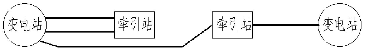
[0039] Such as Figure 7 As shown, a railway traction station power grid access structure provided in Embodiment 1 includes a first substation 1 and a second substation 2, and is located between the first substation 1 and the second substation 2 along the first The first railway traction station 31 and the second railway traction station 32 are arranged in sequence from the substation 1 to the second substation 2, and the first substation 1 and the first railway traction station 31 are connected by a double circuit that can be cut off and switched The line is electrically connected, the incoming line bus of the first railway traction station 31 and the incoming line side bus of the second railway traction station 32 are electrically connected through a single circuit circuit that can be cut off, and the second railway traction The station 32 is electrically connected with the second substation 2 through a disconnectable single circuit line.
[0040] Among them, the first rail...
Embodiment 2
[0048] Such as Figure 10 As shown, embodiment 2 is roughly the same as embodiment 1, and the main difference between the two is that: a third railway traction station 33 is also included, and the third railway traction station 33 is connected to the first substation 1 through a double circuit The line is electrically connected; or the double-circuit line passed between the third railway traction station 33 and the second substation 2 is electrically connected. Specifically, the third railway traction station 33 is electrically connected to the second substation 2 through a switchable and disconnectable double-circuit line. Among them, such as Figure 4 with Figure 10 In contrast, this setting method saves part of the wiring layout and has a good application prospect.
Embodiment 3
[0050] Such as Figure 11 As shown, embodiment 3 is roughly the same as embodiment 1, and the main difference between the two is that: a third railway traction station 33 and a fourth railway traction station 34 are also included, and the first substation 1 and the third railway traction station 33 are electrically connected through a double-circuit line, and the third railway traction station 33 and the fourth railway traction station 34 are electrically connected through a single-circuit line, and the fourth railway traction station 34 is connected to the second substation 2 Each railway traction station is located between the first substation 1 and the second substation 2, and each railway traction station follows the direction from the first substation 1 to the second substation 2, with the first railway traction The station 31, the fourth railway traction station 34, the second railway traction station 32 and the third railway traction station 33 are arranged in sequence....
PUM
 Abstract
Description
Claims
Application Information