

Hydraulic flexible robot joint and robot
A robot joint and flexible technology, applied in the field of robotics, can solve the problem of insufficient flexibility of adjustment
- Summary
- Abstract
- Description
- Claims
- Application Information
AI Technical Summary
Problems solved by technology
Method used
Image

Examples
Embodiment 1
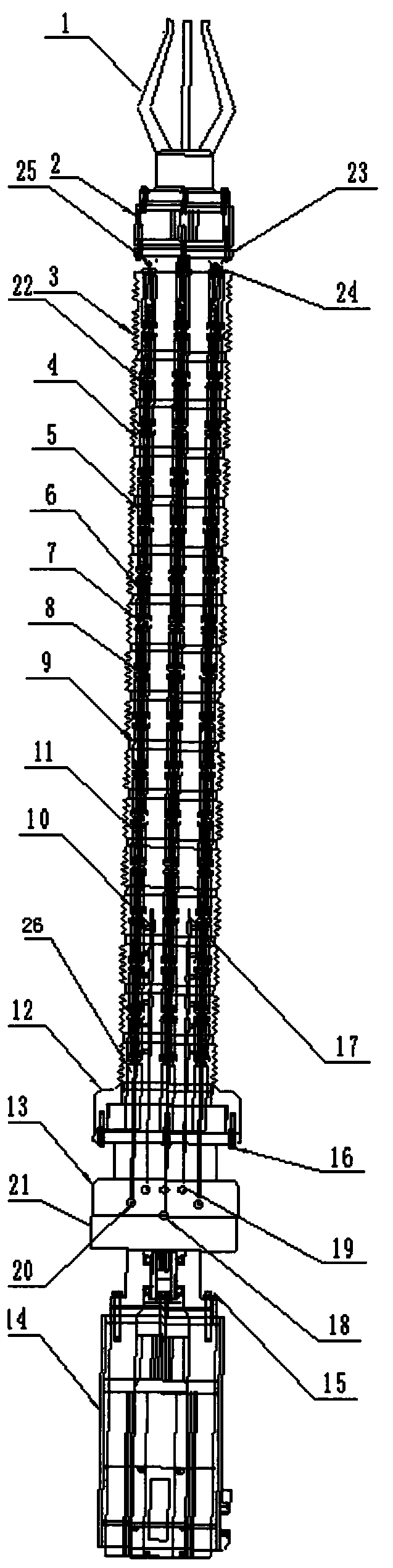
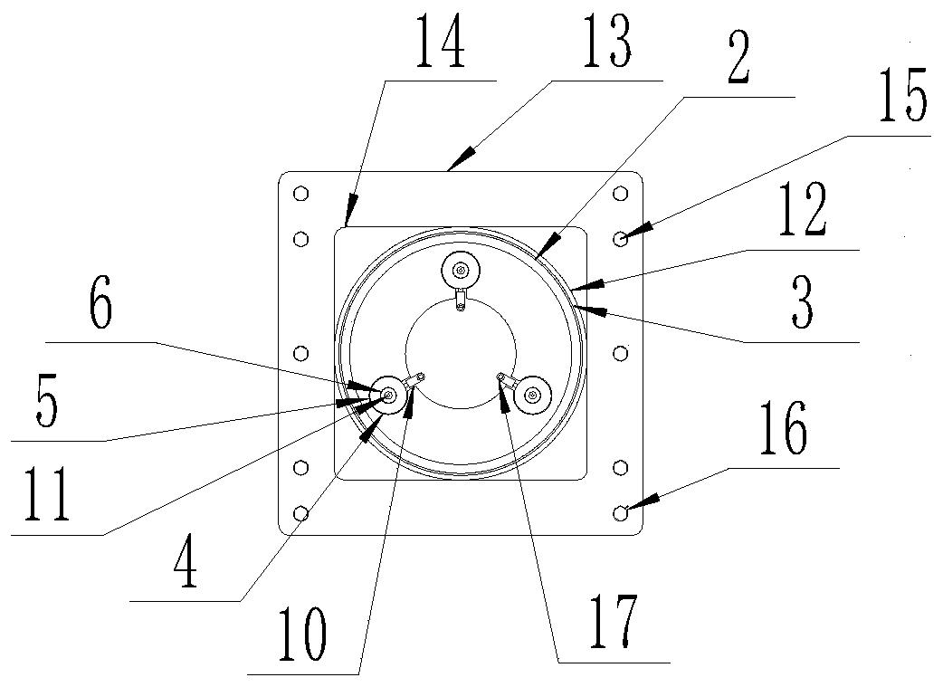
[0024] according to Figure 1-2 The hydraulic flexible robot joint shown is characterized in that it includes a power mechanism, a hydraulic distribution part and an actuator; the power mechanism is connected to the actuator through a hydraulic distribution part; the actuator includes at least multiple sets of power transmission units, The power transmission unit is composed of a plurality of hydraulic cylinders 5 connected in series, and the power mechanism provides power for the hydraulic cylinders 5 of the actuator through hydraulic distribution parts.
[0025] Preferably, the power mechanism is composed of a hydraulic pump motor 14 and a hydraulic pump 21 , and the hydraulic pump motor 14 is connected to the hydraulic distributor through the hydraulic pump 21 .
[0026] Preferably, the hydraulic distribution part is a hydraulic distribution valve 13, and the hydraulic distribution valve 13 is connected with the power mechanism.
[0027] Preferably, the hydraulic distribut...
Embodiment 2
[0039] according to Figure 1-2 The hydraulic flexible robot joint shown is different from the first embodiment in that: the power mechanism is composed of a hydraulic pump motor 14 and a hydraulic pump 21, and the actuator also includes a telescopic bellows 3 and an end plate 23 And the end plate connecting plate 25, the power transmission unit is provided with three groups; the hydraulic pump motor 14 is connected with the hydraulic distribution part through the hydraulic pump 21; the hydraulic distribution part is the hydraulic distribution valve 13, and the hydraulic distribution valve 13 is connected to the hydraulic pump 21; the hydraulic distribution valve 13 is provided with a circuit interface 19 and an output interface 20, the output interface 20 is connected with an output oil pipe 18, the circuit interface 19 is connected with a circuit oil pipe 17, and the circuit oil pipe 17 A plurality of hydraulic pipe tees 10 are connected to it, and the return oil pipe 17 is ...
Embodiment 3
[0043] according to figure 1 The shown robot includes a hydraulic flexible robot joint, and a manipulator 1 is connected to the front end of the hydraulic flexible robot joint through a servo motor 2 .
[0044] In actual use, when the hydraulic cylinder ram 6 moves, the angle of the end plate 23 can be directly adjusted, and the rotation of the servo motor 2 makes the manipulator 1 easier to operate; The front end of the cylinder jack rod 6 is closely matched with the hydraulic cylinder body 5, while the diameter of the rear end is reduced according to a certain ratio to match the sealing ring 22. The return oil pipe 17 is arranged in the diameter of the telescopic bellows 3, and passes through the hydraulic pipe tee 10, respectively. Transmission to each hydraulic cylinder block 5, when the hydraulic pump motor 14 works, the hydraulic pump 21 is driven to generate high-pressure oil fluid, which passes through the hydraulic distribution valve 13 through the hydraulic oil circu...
PUM
 Abstract
Description
Claims
Application Information