Supercharge Your Innovation With Domain-Expert AI Agents!

Simple detection device for measuring response time of traction machine brake

A machine brake and response time technology, applied in the field of detection devices, can solve the problems of being inseparable from the traction machine, time-consuming and laborious detection, inconvenient use, etc., and achieve the effect of simple detection device, easy to use, and improved practicability

Pending Publication Date: 2019-12-27
CANNY ELEVATOR
View PDF0 Cites 0 Cited by
  • Summary
  • Abstract
  • Description
  • Claims
  • Application Information

AI Technical Summary

Problems solved by technology

[0002] Elevator refers to the permanent transportation equipment that serves several specific floors in the building, and its car runs on at least two rigid rails that are perpendicular to the horizontal plane or less than fifteen degrees from the plumb line. With the development of the economy, With the progress of society, elevators are widely used as a means of vertical transportation. The operation of elevators is usually inseparable from the traction machine. As a safety component of the elevator, the brake can brake the traction machine. The braking response time is an important indicator. If the response time is too long, it will directly affect the safety performance of the elevator. The traditional detection device is detected by the torque sensor and the oscilloscope. Since the torque value of the torque sensor needs to be read during the detection, the traction machine must be docked. on the torque sensor, resulting in time-consuming and labor-intensive detection, which is inconvenient to use

Method used


Image

  • Simple detection device for measuring response time of traction machine brake
  • Simple detection device for measuring response time of traction machine brake
  • Simple detection device for measuring response time of traction machine brake

Examples


Embodiment

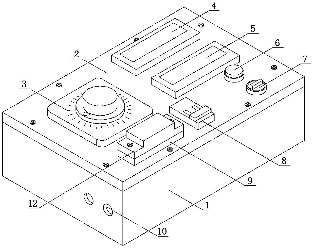
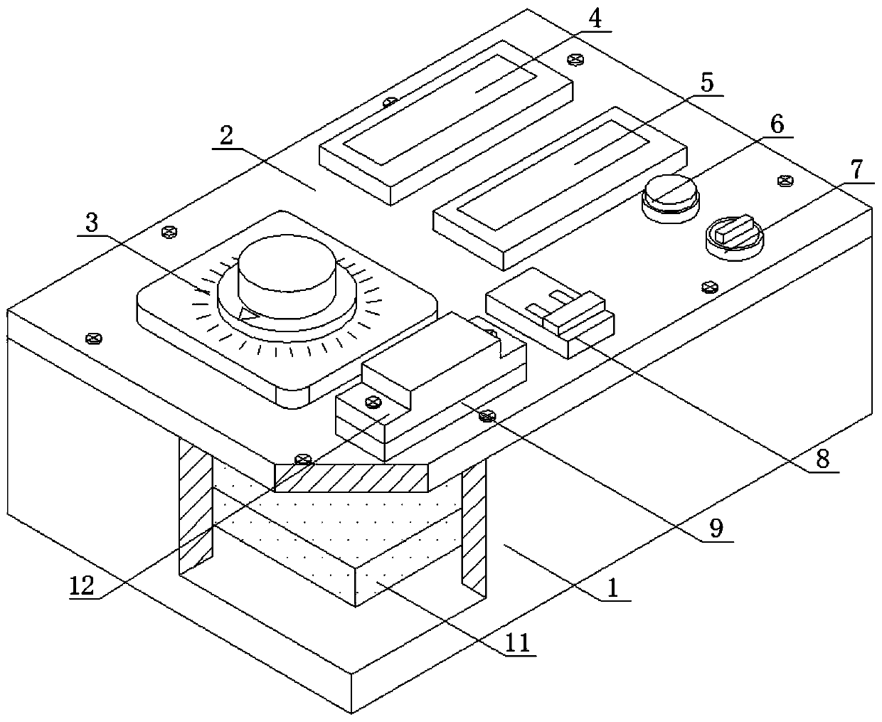
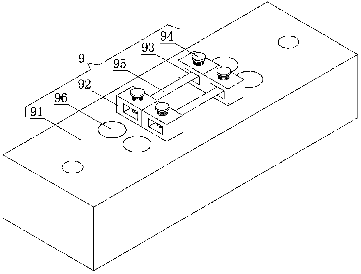
[0019] Example: such as figure 1 , figure 2 with image 3 As shown, a simple detection device for measuring the response time of a traction machine brake of the present invention includes a box body 1, a rectifier plate 11 is provided at the bottom of the inner cavity of the box body 1, and a box cover 2 is connected to the top of the box body 1 by bolts. The top of the box cover 2 is embedded with a voltage regulator 3, a DC voltmeter 4, a microcomputer chronograph 5, a reset switch 6, a double-layer switch 7, a double air switch 8 and an overload protection mechanism 9, and the top of the overload protection mechanism 9 passes The bolt is connected with an insulating protective cover 12, the overload protection mechanism 9 is located under the voltage regulator 3, the DC voltmeter 4 is located on the right side of the voltage regulator 3, the microcomputer chronograph 5 is located under the DC voltmeter 4, and the reset switch 6 is located on the microcomputer Between the ch...


PUM


Abstract

The invention discloses a simple detection device for measuring response time of a traction machine brake. The device comprises a box body, a rectifying plate is arranged on the bottom of an inner cavity of the box body, the top of the box body is connected with a box cover through a bolt, a voltage regulator, a direct-current voltmeter, a microcomputer chronograph, a reset switch, a dual-layer switch, a ganged air switch and an overload protection mechanism are embedded on the top of the box cover, the overload protection mechanism is located below the voltage regulator, and the top of the overload protection mechanism is connected with an insulation protection cover through a bolt. When a brake power source in the dual-layer switch is cut off, the dual-layer switch gives a timekeeping signal to the microcomputer chronograph, at the moment, after the brake is in place, a microswitch on the brake acts, the microswitch gives a timekeeping stop signal to the microcomputer chronograph, atthe moment, the microcomputer chronograph stops work, through observing of the numerical value of the microcomputer chronograph, the response time of the brake can be obtained, the detection processsaves time and labor, and an operator can easily uses the device.

Description

Technical field [0001] The invention relates to a detection device, in particular to a simple detection device for measuring the response time of a traction machine brake. Background technique [0002] Elevator refers to a permanent transportation equipment that serves several specific floors in a building, and its car runs on at least two rows of rigid rails that are perpendicular to the horizontal plane or whose inclination angle to the plumb line is less than 15 degrees. With the development of economy, With the advancement of society, elevators are widely used as vertical vehicles. The operation of elevators is usually inseparable from the traction machine. As a safety component of the elevator, the brake can brake the traction machine. The braking response time is an important indicator. If the response time is too long, it directly affects the safety performance of the elevator, and the traditional detection device is detected by the torque sensor and the oscilloscope. Sinc...

Claims


Application Information

Patent Timeline
Patent Type & Authority Applications(China)
IPC IPC(8): B66B5/00G01M13/00
CPCB66B5/0037G01M13/00
Inventor 李革丁爱芹
Owner CANNY ELEVATOR
Features
  • R&D
  • Intellectual Property
  • Life Sciences
  • Materials
  • Tech Scout
  • Unparalleled Data Quality
  • Higher Quality Content
  • 60% Fewer Hallucinations
Learn More