
Brake disc protective cover and brake disc assembly

A technology for a protective cover and a brake disc, applied in the field of auto parts, can solve the problems of weak structural strength of flat surface parts, aggravated friction lining loss, easy to cause deformation, etc., and achieves good heat dissipation effect and improves heat dissipation effect.

Pending Publication Date: 2019-12-27
恒大恒驰新能源汽车科技(广东)有限公司
View PDF0 Cites 1 Cited by
  • Summary
  • Abstract
  • Description
  • Claims
  • Application Information

AI Technical Summary

Problems solved by technology

[0002] Floating caliper disc brakes are widely used in cars due to their light weight, simple structure, stable braking effect, and easy self-adjustment of brake clearances. Foreign matters such as foreign matter enter the friction position between the friction plate and the brake disc through the gap of the floating caliper, which will increase the loss of the friction plate and affect the braking performance. Therefore, a sheet metal part that matches the shape of the floating caliper disc brake is often designed to prevent debris entry guard
[0003] However, because the wrapping effect of the protective device often affects the heat dissipation of the floating caliper disc brake, the braking effect is weakened; and due to the large diameter of the brake disc, in order to perfectly protect the brake disc, the protective device is often designed as a flat surface part. Flat surface parts usually have weak structural strength and are easy to cause deformation

Method used


Image

  • Brake disc protective cover and brake disc assembly
  • Brake disc protective cover and brake disc assembly
  • Brake disc protective cover and brake disc assembly

Examples


Embodiment Construction

[0041] The specific implementation manner of the present application will be further described below in conjunction with the accompanying drawings. Wherein the same components are denoted by the same reference numerals. It should be noted that the words "front", "rear", "left", "right", "upper" and "lower" used in the following description refer to the directions in the drawings, and the words "inner" and "outer ” refer to directions towards or away from the geometric center of a particular part, respectively.

[0042] The "inner" involved in this application refers to the direction in which the brake disc guard faces the middle of the vehicle during installation, and the "outer" involved in this application refers to the direction in which the brake disc guard faces to the outside of the vehicle; The "front" involved in the above refers to the direction towards the front of the vehicle during installation, and the "rear" involved in this application refers to the direction t...


PUM


Abstract

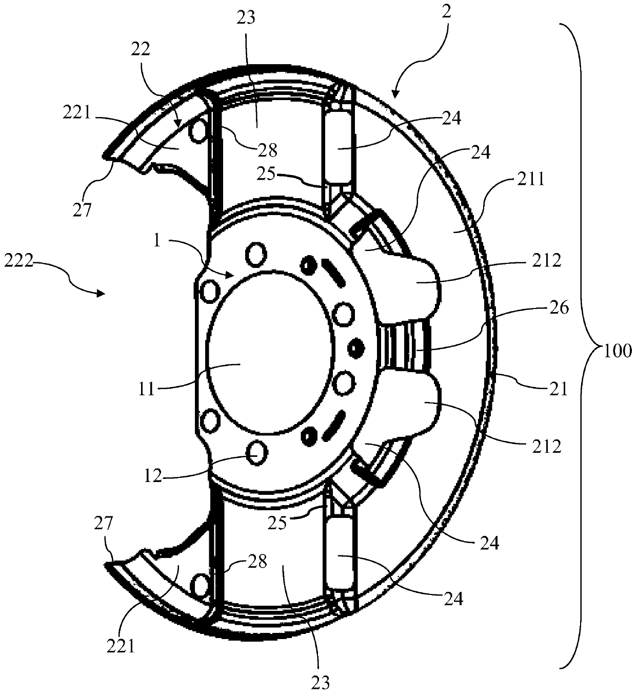
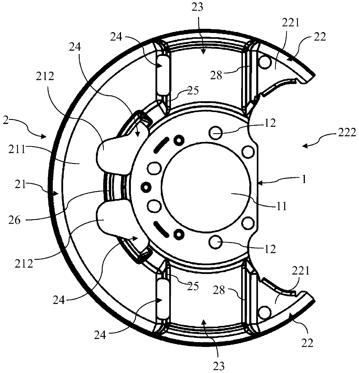
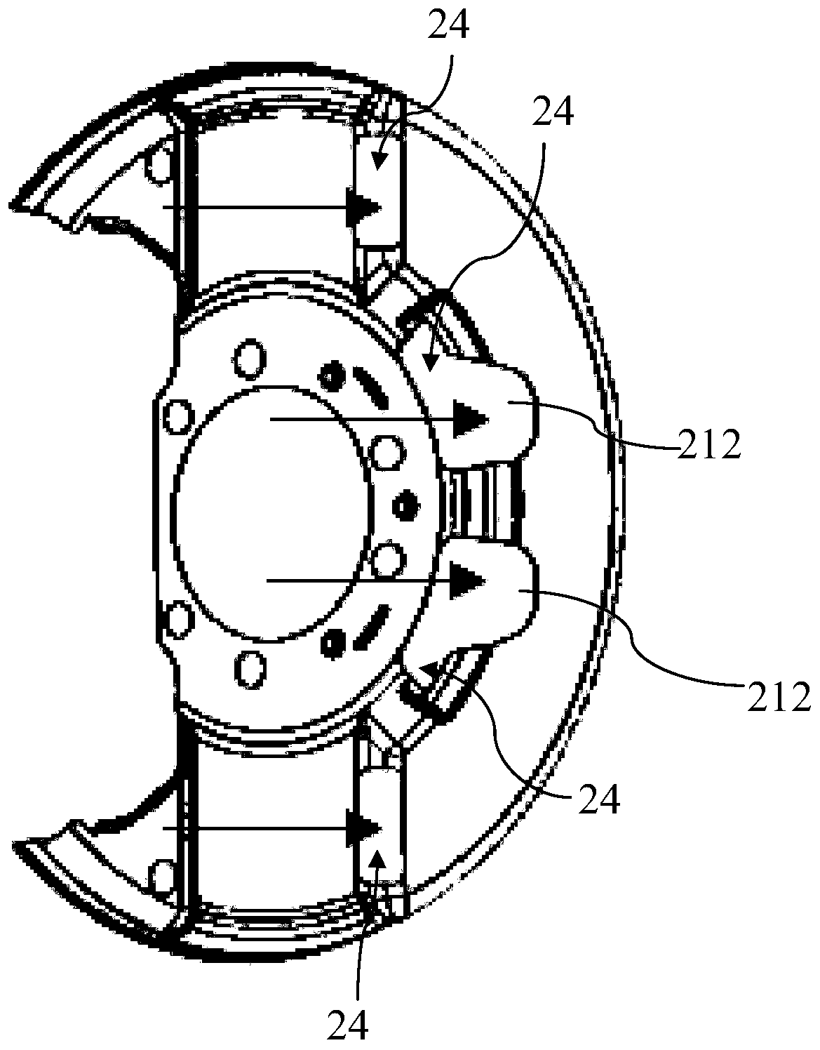
The invention discloses a brake disc protective cover and a brake disc assembly. The brake disc protective cover comprises a mounting disc and an annular protective cover body, wherein the protectivecover body is arranged on the mounting disc, the protective cover body comprises a first arc-shaped cover body, a second arc-shaped cover body and two oppositely-arranged protective cover flat plates,the two protective cover flat plates are oppositely arranged on the upper side and the lower side of the mounting disc correspondingly, the first cover body is connected between the front ends of thetwo protective cover flat plates, and the second cover body is connected between the rear ends of the two protective cover flat plates; and a cover body notch part used for allowing a caliper to be arranged is arranged at the rear part of the second cover body, the first cover body and the second cover body are arranged in an inward protruding mode on the protective cover flat plates correspondingly, and at least one ventilation hole is formed in the side, facing the second cover body, of the first cover body. The brake disc protective cover and the brake disc assembly have the ventilation function, so that the heat dissipation effect is improved, and the braking performance is improved.

Description

technical field [0001] The present application relates to the technical field of auto parts, in particular to a brake disc protective cover and a brake disc assembly. Background technique [0002] Floating caliper disc brakes are widely used in cars due to their light weight, simple structure, stable braking effect, and easy self-adjustment of brake clearances. Foreign matters such as foreign matter enter the friction position between the friction plate and the brake disc through the gap of the floating caliper, which will increase the loss of the friction plate and affect the braking performance. Therefore, a sheet metal part that matches the shape of the floating caliper disc brake is often designed to prevent debris Entry guards. [0003] However, because the wrapping effect of the protective device often affects the heat dissipation of the floating caliper disc brake, the braking effect is weakened; and due to the large diameter of the brake disc, in order to perfectly ...

Claims


Application Information

Patent Timeline
IPC IPC(8): F16D65/00F16D65/847F16D55/22
CPCF16D55/22F16D65/005F16D65/847F16D2055/0037
Inventor 刘萌宋振翔李敬豪
Owner 恒大恒驰新能源汽车科技(广东)有限公司
Learn More