A monitoring method, device and system for bridge deflection based on visual perception
A bridge deflection and visual perception technology, applied in the field of image processing, can solve the problems of the visual sensor being far away from the monitoring point, large monitoring errors, image jitter, etc., and achieve the effect of not being easy to interfere with the environment, reducing low-frequency interference, and improving accuracy
- Summary
- Abstract
- Description
- Claims
- Application Information
AI Technical Summary
Problems solved by technology
Method used
Image
Examples
Embodiment 1
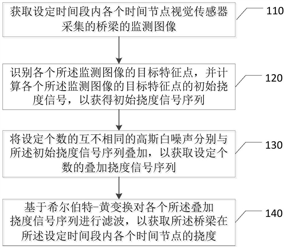
[0025] figure 1 It is a flow chart of a bridge deflection monitoring method based on visual perception provided by Embodiment 1 of the present invention. This embodiment is applicable to the monitoring of bridge deflection. The method can be executed by a bridge deflection monitoring device or system. The device can be realized by means of software and hardware, such as figure 1 As shown, the method specifically includes the following steps:
[0026] Step 110, acquiring monitoring images of the bridge collected by the visual sensor at each time node within the set time period.
[0027] Among them, visual sensors include cameras and lenses. Supports such as tripods and tall poles may also be included. The set time period can be 30s, 45s, 60s or other values, and the time node refers to the interval time for the visual sensor to collect a frame of image.
[0028] Optionally, the monitoring image includes a two-dimensional code pattern.
[0029] Further, the two-dimensional ...
Embodiment 2
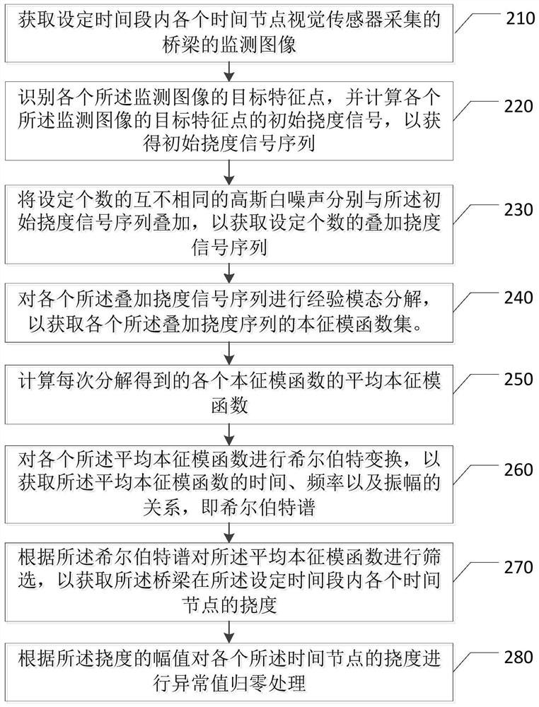
[0059] figure 2 It is a flow chart of a monitoring method for bridge position deflection based on visual perception provided by Embodiment 2 of the present invention. This embodiment is a further refinement of the previous embodiment, such as figure 2 As shown, the method includes the following steps:
[0060] Step 210, acquiring monitoring images of the bridge collected by the visual sensor at each time node within the set time period.
[0061] Step 220: Identify the target feature points of each of the monitoring images, and calculate the initial deflection signals of the target feature points of each of the monitoring images, so as to obtain an initial deflection signal sequence.
[0062] Step 230 : Superimpose a set number of different Gaussian white noises on the initial deflection signal sequence to obtain a set number of superimposed deflection signal sequences.
[0063] Step 240 , performing empirical mode decomposition on each of the superimposed deflection signal...
Embodiment 3
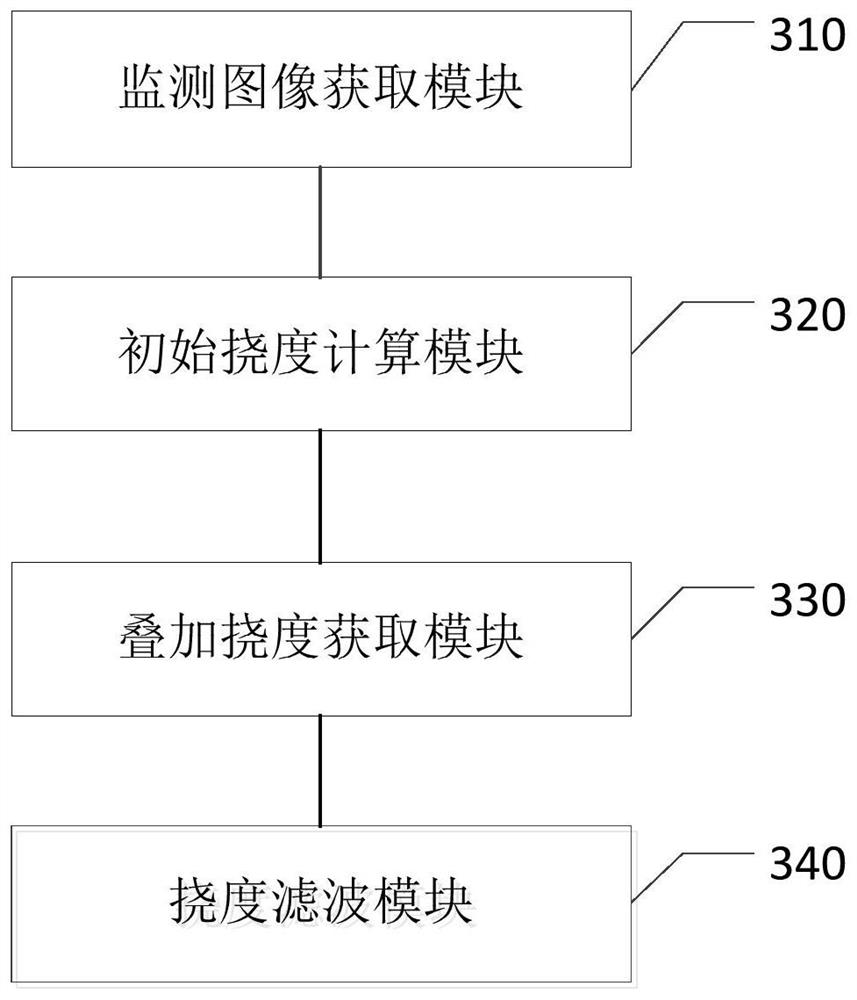
[0103] image 3 It is a schematic diagram of a bridge deflection monitoring device based on visual perception provided by Embodiment 3 of the present invention, as image 3 As shown, the device includes: a monitoring image acquisition module 310 , an initial deflection calculation module 320 , an overlay deflection acquisition module 330 and a deflection filtering module 340 .
[0104] Among them, the monitoring image acquisition module 310 is used to obtain the monitoring images of the bridge collected by the visual sensor at each time node within the set time period; the initial deflection calculation module 320 is used to identify the target feature points of each of the monitoring images, and calculate each The initial deflection signal of the target feature point of the monitoring image to obtain an initial deflection signal sequence; the superimposed deflection acquisition module 330 is used to superimpose a set number of different Gaussian white noises with the initial ...
PUM
 Abstract
Description
Claims
Application Information
 - R&D
- Intellectual Property
- Life Sciences
- Materials
- Tech Scout
- Unparalleled Data Quality
- Higher Quality Content
- 60% Fewer Hallucinations
Browse by: Latest US Patents, China's latest patents, Technical Efficacy Thesaurus, Application Domain, Technology Topic, Popular Technical Reports.
© 2025 PatSnap. All rights reserved.Legal|Privacy policy|Modern Slavery Act Transparency Statement|Sitemap|About US| Contact US: help@patsnap.com


