Supercharge Your Innovation With Domain-Expert AI Agents!

mpo fiber optic connector

An optical fiber connector and inner housing technology, which is applied in the field of MPO optical fiber connectors, can solve the problems such as the connection failure of the optical fiber connector, and achieve the effect of solving the loosening of the hook

Active Publication Date: 2021-03-23
CHINA AVIATION OPTICAL-ELECTRICAL TECH CO LTD
View PDF1 Cites 0 Cited by
  • Summary
  • Abstract
  • Description
  • Claims
  • Application Information

AI Technical Summary

Problems solved by technology

[0004] The purpose of the present invention is to provide an MPO fiber optic connector, which is used to solve the problem in the prior art that the hook is loosened due to the deformation of the cantilever of the spring limit seat, which leads to the failure of the connection of the fiber optic connector.

Method used


Image

  • mpo fiber optic connector
  • mpo fiber optic connector
  • mpo fiber optic connector

Examples


Embodiment Construction

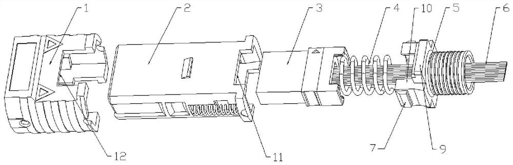
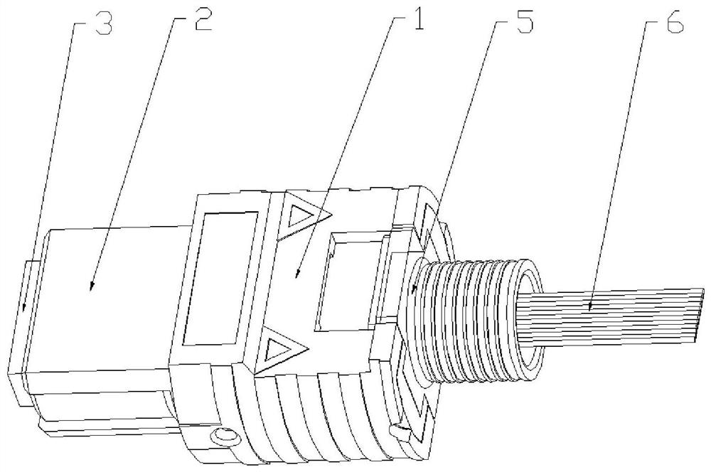
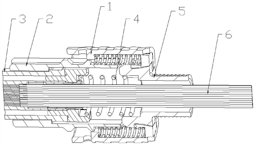
[0020] Embodiments of the MPO fiber optic connector of the present invention are as follows Figure 1 to Figure 3 As shown, it includes an outer shell 1 and an inner shell 2 that make up the outer shell assembly. The inner shell 2 has an inner cavity extending along the front and rear directions. The cross section of the inner shell 2 is rectangular, and the long side direction defining the rectangle is the MPO optical fiber In the left and right direction of the connector, there is a ferrule 3 and a spring 4 for pushing the ferrule 3 in the inner cavity. A locking protrusion 7 protruding from the protruding arm 10 is provided, and the locking protrusion 7 forms a locking structure with the groove 8 on the inner housing 2 .

[0021] The concrete structure of spring limit seat 5 is as Figure 4 As shown, the spring limit seat 5 includes a limit seat body, the limit seat body is composed of a base part and convex arms 10 on the left and right sides of the base part, and the bas...


PUM


Abstract

The invention relates to an MPO (Multi-fiber Push On) optical fiber connector. The connector comprises an inner shell and an outer shell movably sleeved on the inner shell back and forth, wherein theinner shell is provided with an inner cavity; a core insert, a spring and a spring limiting seat which is used for limiting the spring are disposed in the inner cavity; the spring limiting seat is inserted at a rear of the inner cavity; the spring limiting seat comprises a limiting seat body; a side surface of the limiting seat body is provided with a buckling bulge in interference fit with a cavity wall of the inner cavity when the spring limiting seat is inserted into the inner shell; and a side wall of the inner shell is provided with a buckling recess in snap fit with the buckling bulge when the spring limiting seat is assembled in position. The spring limiting seat and the inner shell are connected together in a forced assembly manner, and the spring limiting seat compresses the spring located in the inner shell. Compared with the prior art, the spring limiting seat in the invention is not subject to compressive deformation in the forced assembly process, and the problem of connection failure of the optical fiber connector caused by loosening of a hook due to deformation of a cantilever in the prior art is solved.

Description

technical field [0001] The invention relates to an MPO optical fiber connector. Background technique [0002] With the rapid development of data communications such as big data and cloud computing, the requirements for network bandwidth are increasing in a blowout manner, which in turn puts forward higher requirements for the density of optical fiber networks. Traditional optical fiber wiring and wiring cannot meet the needs of development. Optical fiber connectors can realize the connection, distribution, and transfer between different optical fibers. Among them, the MPO series optical fiber connectors have many advantages such as high connection density, stable and reliable performance, small size, convenient operation, and easy wiring management. They are widely used in signal field of transmission or data transmission. [0003] An optical fiber connector is disclosed in the utility model patent with the authorized notification number CN202453542U, which includes an oute...

Claims


Application Information

Patent Timeline
Patent Type & Authority Patents(China)
IPC IPC(8): G02B6/38
CPCG02B6/3807
Inventor 王金殿姚琦李智乐田兵兵朱双亚孙亚磊
Owner CHINA AVIATION OPTICAL-ELECTRICAL TECH CO LTD
Features
  • R&D
  • Intellectual Property
  • Life Sciences
  • Materials
  • Tech Scout
  • Unparalleled Data Quality
  • Higher Quality Content
  • 60% Fewer Hallucinations
Learn More