Eureka AIR delivers breakthrough ideas for toughest innovation challenges, trusted by R&D personnel around the world.

Resonant converter and control method

A technology of resonant converter and control method, which is applied in the direction of control/regulation system, instrument, DC power input conversion to DC power output, etc.

Active Publication Date: 2019-12-27
DELTA ELECTRONICS INC
View PDF4 Cites 0 Cited by
  • Summary
  • Abstract
  • Description
  • Claims
  • Application Information

AI Technical Summary

Problems solved by technology

[0005] The invention provides a resonant converter and a control method to solve the technical problem of how to reduce the switching frequency while realizing the ZVS of the primary switching tube under light load, thereby greatly improving the light load efficiency

Method used


Image

  • Resonant converter and control method
  • Resonant converter and control method
  • Resonant converter and control method

Examples


Embodiment Construction

[0070] In order to make the purpose, technical solutions and advantages of the embodiments of the present invention clearer, the technical solutions in the embodiments of the present invention will be clearly and completely described below in conjunction with the drawings in the embodiments of the present invention. Obviously, the described embodiments It is a part of embodiments of the present invention, but not all embodiments. Based on the embodiments of the present invention, all other embodiments obtained by persons of ordinary skill in the art without creative efforts fall within the protection scope of the present invention.

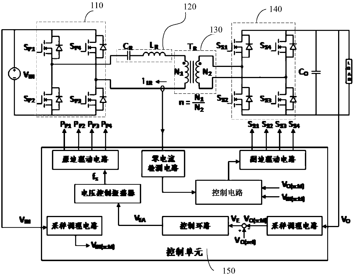
[0071] figure 1 It is a circuit diagram of a resonant converter proposed according to an embodiment of the present invention. Such as figure 1 As shown, a resonant converter provided in this embodiment is suitable for providing an output voltage to a load, wherein the resonant converter includes: a primary circuit 110, a resonant network 120, a ...


PUM


Abstract

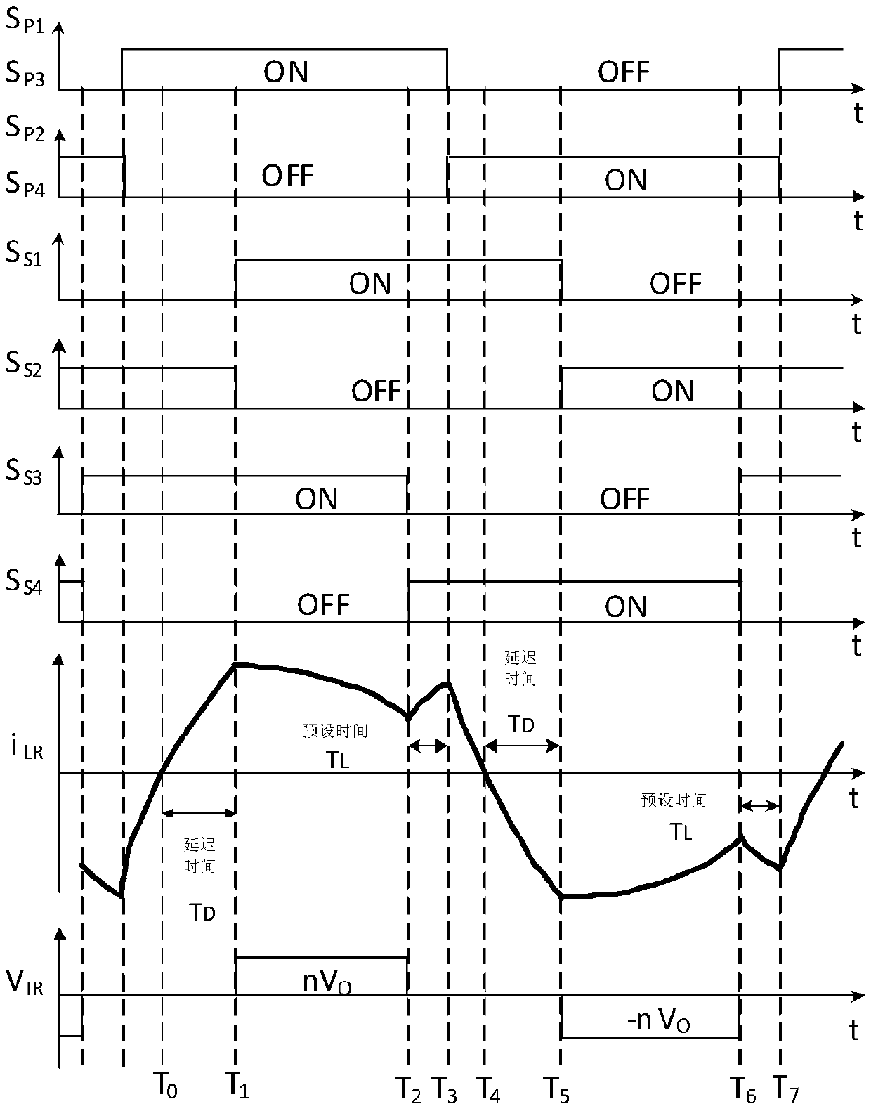
The invention provides a resonant converter and a control method. The resonant converter is suitable for providing an output voltage to a load. The resonant converter comprises a primary side circuit,the resonance network, a transformer, a secondary side circuit and a control unit, wherein the primary side circuit comprises at least one group of primary side switches and is used for receiving aninput voltage, the resonance network is coupled to the primary side circuit, the transformer is provided with a primary winding and a secondary winding, the primary winding is coupled with the resonance network, the secondary side circuit comprises at least one group of secondary side switches, the secondary side circuit is coupled to the secondary side winding of the transformer, the control unitis used for controlling a switching state of a secondary side switch according to the input voltage, the output voltage and a preset time before the switching moment of the primary side switch state,so the secondary side winding of the transformer is short-circuited, a relatively large negative current is generated, and the soft switching condition is created for a primary side switch tube. Theresonant converter is advantaged in that soft turn-on of the primary side switching tube under a light load can be realized, and the resonant converter is more suitable for a wide voltage range.

Description

technical field [0001] The invention relates to the technical field of power electronic conversion, in particular to a resonant converter and a control method. Background technique [0002] The traditional resonant converter has the advantage of realizing the Zero Voltage Switch (ZVS for short) of the primary switching tube, and is widely used in high-efficiency, high-frequency and high-power-density occasions. However, in applications with a wide voltage range (wide input voltage or wide output voltage range), resonant converters have problems such as wide switching frequency range, difficulty in optimizing efficiency design, and large magnetic parts, which make traditional resonant converters It is difficult to achieve good performance across a wide voltage range. [0003] At present, more and more researches are focused on resonant converters suitable for wide voltage range. Most of the research work is to expand the voltage range of the resonant converter on the basis ...

Claims


Application Information

Patent Timeline
IPC IPC(8): H02M3/335
CPCH02M3/33576H02M3/33523H02M3/33592Y02B70/10Y02P80/10H02M3/01H02M3/015H02M1/083H02M1/0009H02M1/0032H02M1/0058
Inventor 魏涛卢昊
Owner DELTA ELECTRONICS INC
Why Eureka
Eureka Blog
Learn More