
Parallel wind power converter system and control method thereof

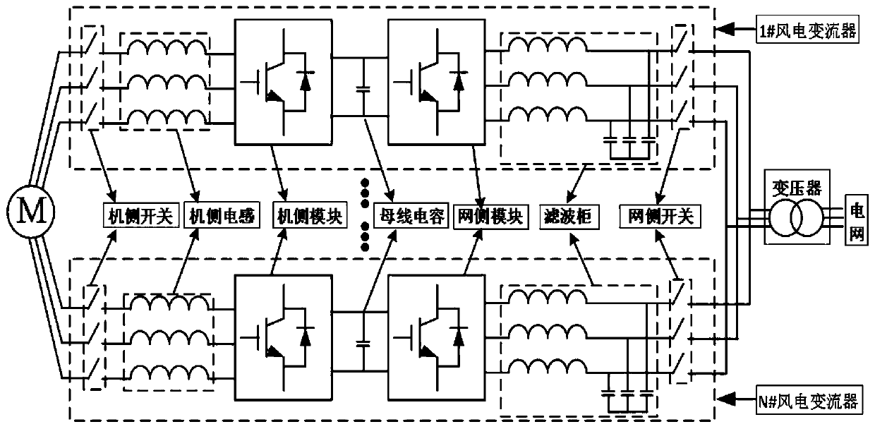
A technology of a wind power converter and a control method, which is applied to wind power generation, printed circuit board sockets, conversion equipment for intermediate conversion to direct current, etc., and can solve problems such as shutdown switching interrupt operation, large line loss, and affecting efficiency, etc. , to achieve the effect of smooth power flow of the whole machine, optimization of operating efficiency, and reduction of electrical lap points

Inactive Publication Date: 2019-12-27
SHENZHEN HOPEWIND ELECTRIC CO LTD
View PDF2 Cites 1 Cited by
  • Summary
  • Abstract
  • Description
  • Claims
  • Application Information

AI Technical Summary

Problems solved by technology

However, the existing schemes are to cut out or put in the wind power converter in the shutdown state, and for some occasions where the operating conditions change in real time, the shutdown switching will obviously interrupt the operation and affect the efficiency; and for some In the case of high and low voltage ride-through reactive power support requirements, complete removal of a certain machine may cause the entire system to fail to meet the high and low voltage ride through reactive power support requirements
[0006] It can be obtained comprehensively that the existing parallel wind power converter system has unsmooth internal power flow in single-unit layout, high cost, large line loss, and is not flexible enough in redundant control to meet the efficiency and reliability requirements of the wind farm power grid.

Method used


Image

  • Parallel wind power converter system and control method thereof
  • Parallel wind power converter system and control method thereof
  • Parallel wind power converter system and control method thereof

Examples


Embodiment Construction

[0033] Embodiments of the present invention will be described below with reference to the drawings. It should be noted that representation and description of components and processes that are not related to the present invention and known to those of ordinary skill in the art are omitted from the drawings and descriptions for the purpose of clarity.

[0034] In describing the present invention, it should be understood that the terms "center", "longitudinal", "transverse", "upper", "lower", "front", "rear", "left", "right", " The orientations or positional relationships indicated by "vertical", "horizontal", "top", "bottom", "inner" and "outer" are based on the orientations or positional relationships shown in the drawings, and are only for the convenience of describing the present invention and Simplified descriptions, rather than indicating or implying that the device or element referred to must have a particular orientation, be constructed and operate in a particular orienta...


PUM


Abstract

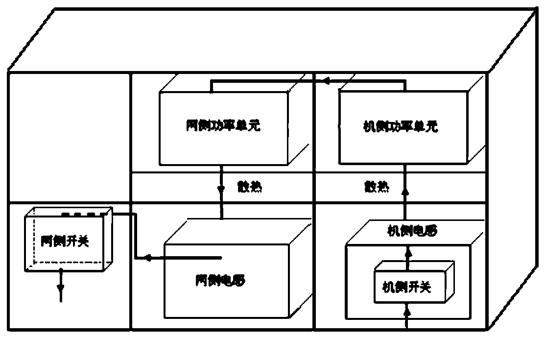
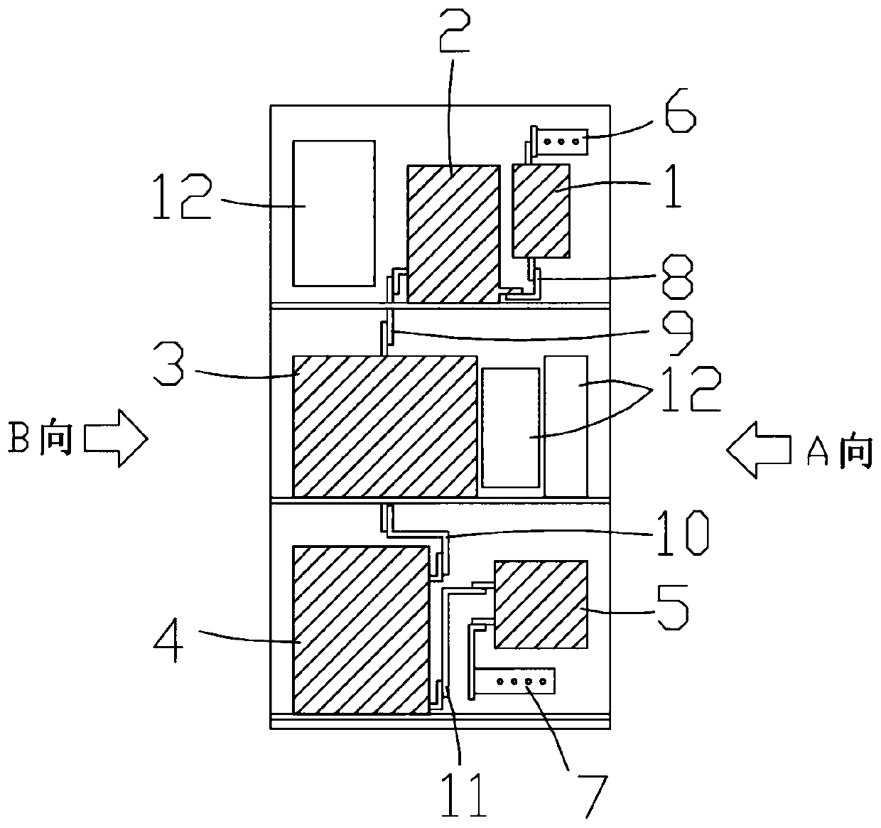
The invention discloses a parallel type wind power converter system, and the system comprises N wind power converters connected in parallel. Each wind power converter comprises a machine side assembly, a power unit assembly and a network side assembly, which are arranged in a longitudinally staggered mode. A wind power converter cabinet body is internally divided into a first space, a second spaceand a third space which are arranged from top to bottom, and the machine side assembly is installed in the first space or the third space in the wind power converter cabinet body; the network side assembly is installed in a first space or a third space in the wind power converter cabinet body. The power unit assembly is installed in the second space in the wind power converter cabinet body. According to the invention, each module of the wind power converters is reasonably arranged; the power flow reaches the power unit assembly from top to bottom from the machine side assembly and then reaches the network side assembly from top to bottom from the power unit assembly, so that the distance of electrical connection and the lap joint of electrical connection are reduced, and the single-machine layout and the online redundant parallel operation strategy of the parallel wind power converter system of the whole machine are reduced.

Description

technical field [0001] The invention relates to the technical field of wind power generation, in particular to a parallel wind power converter system and a control method thereof. Background technique [0002] With the intensification of the fossil energy crisis, the development and utilization of new energy has become a current research hotspot, especially in the field of wind power generation technology, and wind power converters are a key component of wind power generation. The direct-drive wind power converter is widely used in offshore wind power with high reliability requirements due to its characteristics of no gearbox, high reliability, and low maintenance cost. The cost of offshore wind power projects is high. In order to reduce the cost per unit power, large-capacity offshore wind power converters have become a development trend, and parallel wind power converters with multiple machines connected in parallel are a common expansion method. [0003] The parallel win...

Claims


Application Information

Patent Timeline
Patent Type & Authority Applications(China)
IPC IPC(8): H02M5/42H05K7/14H02J3/38
CPCH02M5/42H05K7/1432Y02E10/76
Inventor 喻俊鹏胡斌周党生
Owner SHENZHEN HOPEWIND ELECTRIC CO LTD
Learn More