Split type profile material forming die

A molding die, split type technology, applied in the direction of metal extrusion dies, etc., can solve the problems of poor flatness, affecting the experimental effect of profile forming dies, and low production efficiency

Inactive Publication Date: 2019-12-31
张变妮
View PDF0 Cites 2 Cited by
  • Summary
  • Abstract
  • Description
  • Claims
  • Application Information

AI Technical Summary

Problems solved by technology

[0003] In the prior art, there is no lubricating product installed in the inner cavity of the mold body, and the product formed in this way has the di

Method used


Image

  • Split type profile material forming die
  • Split type profile material forming die

Examples


Embodiment Construction

[0018] The present invention will be further described below in conjunction with the accompanying drawings.

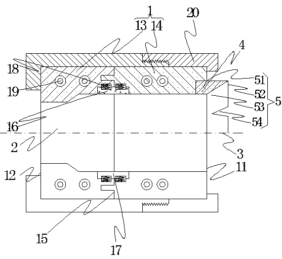
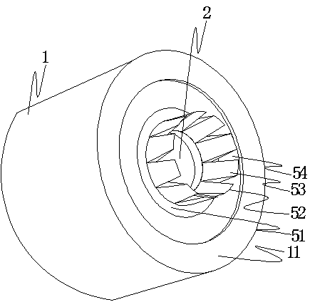
[0019] Such as figure 1 As shown, a split-type profile forming mold includes a mold body 1, the mold body has a molding cavity 2, the mold body has a rear side 11 where molding material enters, and the molding material enters from the molding cavity The front side 12 coming out of the center, the molding inner cavity is the cavity that penetrates from the back side to the front side, and the mold body also has a center connection line 3 connecting the center of the back side and the center of the front side; its characteristics are: The mold body is composed of two molds, the two mold monomers are the front monomer 13 and the rear monomer 14 respectively, and the connecting part of the front monomer and the rear monomer is the junction 15, Their junctions are matched and connected to form the mold body, and the junctions are longitudinally cut into the molding inner c...


PUM


Abstract

The invention relates to the technical field of dies and discloses a split type profile material forming die comprising a die body. The die body is provided with a forming inner cavity. The forming inner cavity is a cavity penetrating through from the rear side to the front side. The die body also has a center connection line connecting the rear side center with the front side center. The die bodyis composed of two dies. The two die single bodies are the front single body at the front and a rear single body in the rear position correspondingly. The connection positions of the front single body and the rear single body are joints. The joints are matched and connected, and the die body is formed. The joints longitudinally cut the forming inner cavity, the joint on the side face of the forming inner cavity is provided with a groove for holding a graphite block, the graphite block is put in the groove, and the surface of the graphite block and the side face of the forming inner cavity form a smooth transition structure after the graphite block is put into the groove. The split type profile material forming die has the advantages that few scratches are generated on the surface of a produced product, flatness is high, and production efficiency is high.

Description

technical field [0001] The invention relates to the technical field of moulds, in particular to profile forming moulds. Background technique [0002] The profile forming mold includes a mold body, the mold body has a molding cavity, the mold body has a rear side where molding materials (such as high-temperature aluminum ingots, PE) enter, and molding materials enter from the molding cavity The front side coming out of the center, the molding inner cavity is the cavity that runs through from the back side to the front side, and the mold body also has a center line connecting the center of the back side and the center of the front side, and the molding material passes through The forming cavity installed on the profile forming machine can form the profile. [0003] In the prior art, there is no lubricating product installed in the inner cavity of the mold body, so the product formed in this way has the disadvantages of more surface scratches, poor flatness, and low production...

Claims


Application Information

Patent Timeline
IPC IPC(8): B21C25/02B21C23/32B21C29/04B29C48/30B29C48/86
CPCB21C23/32B21C25/02B21C29/04B29C48/30B29C48/865
Inventor 张变妮
Owner 张变妮
Why Eureka
Try Eureka