Feeding device for taking and placing materials through air pressure change

A technology of changing air pressure and picking and unloading materials, which is applied in the direction of transportation, packaging, and conveyor objects. It can solve the problems of difficult loading and unloading, positioning and clamping, scratches on the workpiece surface, and high cost, so as to reduce surface scratches and unloading. The effect of fast speed and high positioning accuracy

Pending Publication Date: 2018-05-08
BEIJING JINGDIAO GRP CO LTD
View PDF12 Cites 2 Cited by
  • Summary
  • Abstract
  • Description
  • Claims
  • Application Information

AI Technical Summary

Problems solved by technology

Since the front protruding insert needs to cooperate with the jack, the dimensional accuracy is very high. If the dimensional accuracy is not up to standard, it will affect normal use or cause problems such as poor contact.
However, due to the small size of the plug insert itself, loading and unloading and positioning and clamping are relatively difficult. At present, when the front protruding insert head is finished, the single plug insert is manually inserted into the corresponding positioning jig. On the one hand, this clamping and positioning method is difficult to control the insertion force and direction by manual operation, it is difficult to achieve high positioning accuracy, and it is easy to cause scratches on the surface of the workpiece; High volume and low price production requirements

Method used


Image

  • Feeding device for taking and placing materials through air pressure change
  • Feeding device for taking and placing materials through air pressure change

Examples


Embodiment Construction

[0011] The present invention will be further described in detail below in conjunction with the accompanying drawings and specific embodiments.

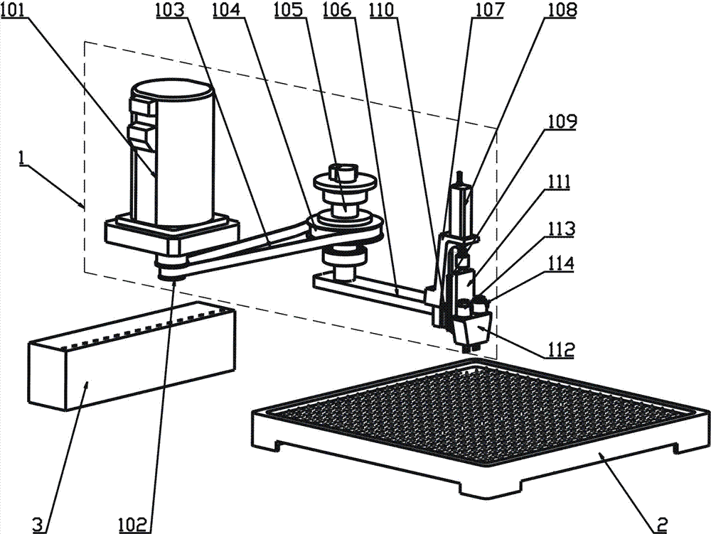
[0012] combine figure 1 with figure 2 As shown, a feeding device of the present invention for picking and discharging materials through changes in air pressure is composed of a feeding manipulator 1, a loading tray 2 and a positioning jig 3, and the loading tray 2 and the positioning jig 3 are respectively arranged on the upper The two sides of material manipulator 1.

[0013] The feeding manipulator 1 comprises a servo motor 101, a small pulley 102, a synchronous belt 103, a large pulley 104, a rotating shaft 105, a swing arm 106, a mounting bracket 107, a cylinder 108, a guide rail 109, a slide block 110, a sliding base plate 111 and a vacuum Suction cup 112. Wherein the servo motor 101, the small pulley 102, the synchronous belt 103, the large pulley 104, the rotating shaft 105 and the swing arm 106 form the drive carrying part...


PUM


Abstract

The invention relates to a feeding device for taking and placing materials through the air pressure change. The feeding device aims to solve the problems that inserting head and inserting piece clamping locating precision and efficiency are low, and the surface is scratched easily. The feeding device is composed of a feeding mechanical hand, a loading tray and a locating jig. The loading tray andthe locating jig are located on the two sides of the feeding mechanical hand correspondingly. The feeding mechanical hand comprises a drive carrying portion and a vertical taking and placing portion.The vertical taking and placing portion can move between the loading tray and the locating jig under driving of the drive carrying portion. The vertical taking and placing portion is composed of an installing support, an air cylinder, a guide rail, a sliding block, a sliding bottom plate and a vacuum sucking disc. The installing support is fixed to the drive carrying portion. The air cylinder is supported on the installing support. The sliding bottom plate is installed on the installing support in a sliding manner through the guide rail and the sliding block and moves up and down under controlling of the air cylinder. The vacuum sucking disc is fixed to the sliding bottom plate. The vacuum sucking disc is provided with a vacuum air way and a positive pressure air way. The vacuum air way isconnected continuously. The positive pressure air way is controlled by an electromagnetic valve to be connected or disconnected.

Description

technical field [0001] The invention belongs to the field of numerical control automation, and in particular relates to a feeding device for taking and discharging materials through changes in air pressure. Background technique [0002] The plug blade structure usually includes three parts: the front protruding blade head, the rear protruding terminal pin and the middle spacer. . Since the front protruding insert needs to cooperate with the socket, the dimensional accuracy is very high. If the dimensional accuracy is not up to standard, it will affect the normal use or cause problems such as poor contact. However, due to the small size of the plug insert itself, loading and unloading and positioning and clamping are relatively difficult. At present, when the front protruding insert head is finished, the single plug insert is manually inserted into the corresponding positioning jig. On the one hand, this clamping and positioning method is difficult to control the insertion ...

Claims


Application Information

Patent Timeline
Patent Type & Authority Applications(China)
IPC IPC(8): B65G47/91
CPCB65G47/914
Inventor 王岱魏志军韩银平王冰旭
Owner BEIJING JINGDIAO GRP CO LTD
Why Eureka
Try Eureka