

Method for molding transverse span shaft of milling machine
A technology for forming and milling machines, applied in milling machine equipment, milling machine equipment details, metal processing equipment, etc., can solve the problems of inconvenient and troublesome operation, low product qualification rate, and too much time consumption, so as to reduce surface scratches and improve Production efficiency and product yield, avoid pin positioning and the effect of upper and lower plate operations
Inactive Publication Date: 2011-01-26
GCI SCI & TECH
View PDF4 Cites 2 Cited by
- Summary
- Abstract
- Description
- Claims
- Application Information
AI Technical Summary
Problems solved by technology
This molding processing method has the following problems: First, each section of the document needs to repeatedly perform pin positioning and upper and lower board operations, which consumes too much time and is inefficient; second, this type of printed board is relatively long and needs to be inserted into the back of the machine. , and the vertical height from the main shaft to the machine is relatively small, generally about 35mm. When loading and unloading boards, because the vertical between the main shaft and the machine is too small, the operation of the printed circuit board is limited to a relatively small space, and it is difficult to avoid dragging Line scratches and surface scratches caused by dragging, coupled with multiple operations of upper and lower boards, lead to a relatively low product qualification rate
The third is that this molding method will bring great inconvenience and trouble to the operation.
Method used
View moreImage
Smart ImageViewing Examples


Examples
Embodiment Construction
Login to View More PUM
 Abstract
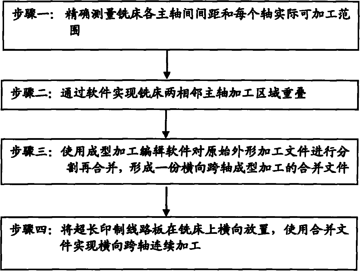
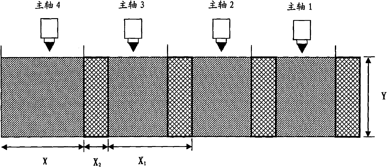
The invention discloses a method for molding a transverse span shaft of a milling machine, which comprises the following steps: (1) measuring the spacing interval between each two main shafts of the milling machine and the actual processable range of each main shaft; (2) realizing the overlapping of processing regions of the adjacent two main shafts of the milling machine through software; (3) using molding editing software to carry out segmentation and re-merging on an original shape processing file and forming a merged file of molding of the transverse span shaft; and (4) transversely placing an ultra-long printed circuit board on the milling machine, and calling the merged file for realizing the continuous processing of the transverse span shaft of the ultra-long printed circuit board. The adoption of the method can lead the ultra-long printed circuit board to continuously complete the molding once on the ordinary multi-shaft milling machine, avoid multi-positioning and plate loading and unloading operation, reduce lines and surface scratches of the circuit, ensure the molding precision and simultaneously improve the production efficiency and the product qualification rate to the maximum extent.
Description
technical field The invention relates to the field of printed circuit board production, in particular to a method for horizontally cross-axis forming processing of a milling machine. Background technique Plate antenna products have always been an indispensable part of the construction of communication base stations. With the continuous development of communication base station construction in rural areas of our country, the demand for plate antennas with high gain and high beamwidth is also increasing. For plate antennas with high gain and high beamwidth, the printed circuit board and the attached shielding cover of the antenna design have the following two important features: First, the length is longer, such as the frequency band 824-966MHz, the gain is 16.5dBi, For a plate antenna with a horizontal beam width of 85°, the length of the printed circuit board and the shielding cover is more than 2.5m. Flower, so as not to affect the signal transmission. The above two fea...
Claims
Login to View More Application Information
Patent Timeline
 Patent Type & AuthorityApplications(China)
IPC IPC(8): B23C3/00
Inventor陈亮任代学王晓伟
OwnerGCI SCI & TECH