Novel multi-tension-testing-rod mould

A technology for tensile test rods and molds, which is applied in the field of aluminum alloy casting, can solve problems such as low pass rate of test rods, shrinkage porosity, and difficult operation, so as to improve yield and mechanical properties, reduce shrinkage porosity defects, and reduce technical required effect

Inactive Publication Date: 2019-12-31
河北立中有色金属集团有限公司
View PDF11 Cites 2 Cited by
  • Summary
  • Abstract
  • Description
  • Claims
  • Application Information

AI Technical Summary

Problems solved by technology

[0002] At present, when casting aluminum alloy tensile test bars, the most used vertical test bar mold is GB / T1173-2013 tensile test bar mold. This mold has strict technical requirements on mold temperature, casting temperature, and casting speed. It is very difficult, and the tensile test rods produced are often accompanied by defects such as slag inclusions, pores, shrinkage porosity, etc., resulting in a low pass rate of the test rods, and the mechanical properties cannot meet the requirements, so re-sampling is required for testing, resulting in repetitive work
[0003] The main disadvantages of the GB / T1173-2013 tensile test bar mold are: ① After three times of normal pouring, the mold temperature is too high, and it needs to cool down before continuing to work, and the work efficiency is low
② Casting test rods have high technical requirements, otherwise the yield and mechanical properties of pouring test rods are low

Method used


Image

  • Novel multi-tension-testing-rod mould
  • Novel multi-tension-testing-rod mould
  • Novel multi-tension-testing-rod mould

Examples


Embodiment Construction

[0024] The following will clearly and completely describe the technical solutions in the embodiments of the present invention with reference to the accompanying drawings in the embodiments of the present invention. Obviously, the described embodiments are only some of the embodiments of the present invention, not all of them. Based on the embodiments of the present invention, all other embodiments obtained by persons of ordinary skill in the art without making creative efforts belong to the protection scope of the present invention.

[0025] In order to make the above objects, features and advantages of the present invention more comprehensible, the present invention will be further described in detail below in conjunction with the accompanying drawings and specific embodiments.

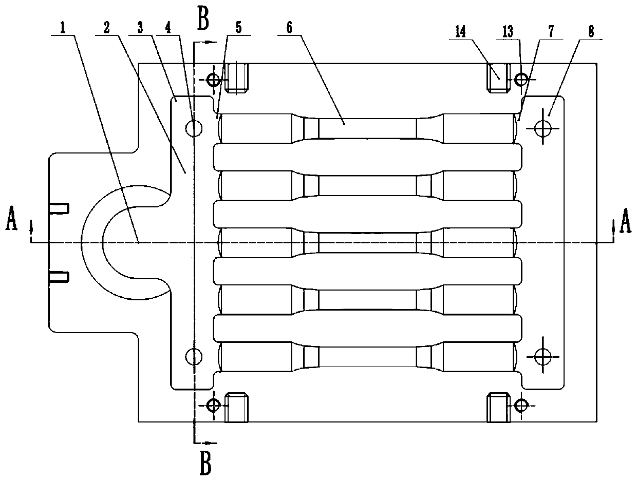
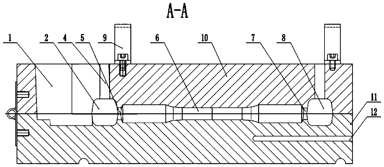
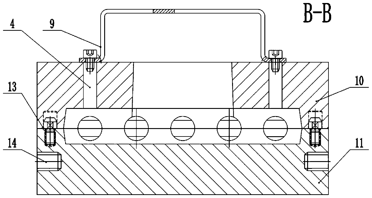
[0026] The present invention provides a new type of multiple tensile test bar mold, the mold includes an upper mold 10 and a lower mold 11, the upper mold 10 and the lower mold 11 are positioned by a ...


PUM

PropertyMeasurementUnit
diameteraaaaaaaaaa
thicknessaaaaaaaaaa

Abstract

The invention discloses a novel multi-tension-testing-rod mould. The mould comprises an upper mould and a lower mould; the upper mould and the lower mould are positioned through a positioning pin andare precisely assembled; one end in the mould is provided with a pouring opening; one side of the pouring opening communicates with a horizontal runner; two axial ends of the horizontal runner are provided with slag collection blind passages; n cavities are sequentially formed in the other side of the horizontal runner in the vertical direction, and n is larger than or equal to 2; one end of eachcavity communicates to the horizontal runner through a direct runner, and the other end communicates with a feeding head through a feeding passage; and the horizontal runner, the direct runners, the cavities, the feeding passages and the feeding head are symmetrically distributed about a contact surface of the upper mould and the lower mould. By adopting the novel multi-tension-testing-rod mould,multiple tension testing rods can be poured at one step; working efficiency is improved, and operation is simple; defects of slag inclusion and pores in the tension testing rods are reduced through arrangement of the slag collection blind passages; two ends of the testing rods can be fed sufficiently through the horizontal runner and the feeding head; very good smoothness of end surfaces is ensured; the defect of shrinkage porosity is lowered; and the yield and mechanical performance of the tension testing rods are improved.

Description

technical field [0001] The invention relates to the field of aluminum alloy casting, in particular to a novel mold with multiple tensile test rods. Background technique [0002] At present, when casting aluminum alloy tensile test bars, the most used vertical test bar mold is GB / T1173-2013 tensile test bar mold. This mold has strict technical requirements on mold temperature, casting temperature, and casting speed. It is very difficult, and the produced tensile test rods are often accompanied by defects such as slag inclusions, pores, shrinkage porosity, etc., resulting in a low pass rate of the test rods, and the mechanical properties cannot meet the requirements, which requires re-sampling and testing, resulting in repetitive work. [0003] The main disadvantages of the GB / T1173-2013 tensile test bar mold are: ① After three normal pours, the mold temperature is too high, and the operation can only be continued after cooling down, and the work efficiency is low. ② Casting ...

Claims


Application Information

Patent Timeline
Patent Type & Authority Applications(China)
IPC IPC(8): B22C9/22B22C9/20B22C9/06B22C9/08
CPCB22C9/06B22C9/082B22C9/088B22C9/20B22C9/22
Inventor 葛素静杜科选宗福春苑高利孟红彦孙芳芳
Owner 河北立中有色金属集团有限公司
Why Eureka
Try Eureka