Driving axle housing waste automatic disassembling device and method

A technology for automatic disassembly and drive axle housing, which is applied in auxiliary devices, plasma welding equipment, program control manipulators, etc., can solve the problems of failure to automatically disassemble different types of drive axle housing waste, potential safety hazards, and low production efficiency. Achieve the effect of eliminating manual unloading process, high production efficiency and high work efficiency

Active Publication Date: 2019-12-31
柳州福臻汽车冲压件有限公司
View PDF4 Cites 2 Cited by
  • Summary
  • Abstract
  • Description
  • Claims
  • Application Information

AI Technical Summary

Problems solved by technology

[0003] The technical problem to be solved by the present invention is: to provide a device and method for automatically dismantling drive axle housing waste to solve the existing problems of low production efficiency, difficulty in taking waste, potential safety hazards, and the ability to automatically disassemble different types of drive axles. Disadvantages of Shell Scrap

Method used


Image

  • Driving axle housing waste automatic disassembling device and method
  • Driving axle housing waste automatic disassembling device and method
  • Driving axle housing waste automatic disassembling device and method

Examples


Embodiment 1

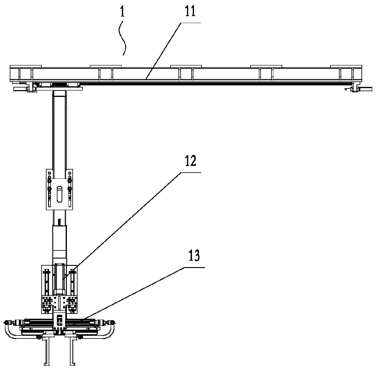
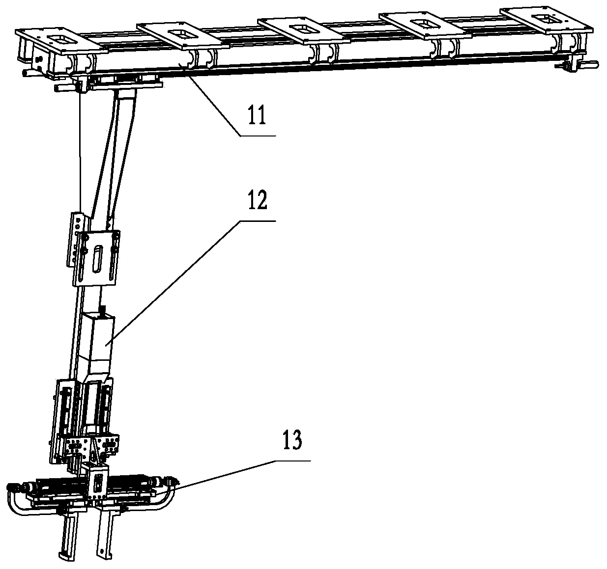
[0075] An automatic dismantling device for drive axle housing waste, including a horizontal hanging device 11, a lifting connection device 12, and a material unloading device 13;

[0076] The horizontal hanging device 11 includes a beam 111, an inductor mounting support 112, an inductor I113, a buffer 114, a sliding table 115, a vertical boom 116, a guide rail I118, a rodless cylinder 119, and a slider I1110; wherein:

[0077] The beam 111 is fixed above the workbench through the fixing block 1111, and the two guide rails I118 are respectively fastened on both sides of the bottom of the beam 111. The guide rails I118 are external double-axis linear square guide rails (standard parts); the described The slider I1110 is slidingly connected with the guide rail I118, the slider I1110 is a high-speed double-roller slide rail slider table (standard part), and the slider I1110 is fixedly connected with the slide table 115; the rodless cylinder 119 is fixed on the bottom of the beam B...

Embodiment 2

[0085] A method for automatically removing drive axle housing waste, the method comprising the steps of:

[0086] S1. Preparation: Clamp the workpiece in place, slide the rodless cylinder in place along -X, and slide the servo electric cylinder in place along -Y; the specific content of this step S1 is:

[0087] Transfer the workpiece drive axle housing 5 with the pre-machined hole 53 to the workpiece clamping positioner 4, the workpiece clamping positioner clamps the workpiece and turns it in place, and ensures the pre-processed hole 53 each time the workpiece is clamped Always maintain a fixed position, so that the unloading device 13 can accurately extend into the pre-processed hole 53 every time, and will not interfere with the device due to differences in workpieces; the signal is input to the automatic removal device 1 for drive axle housing waste, and the rodless cylinder 119 Work, push the sliding table 115 to move in the -X direction, when the end surface of the slidi...


PUM


Abstract

The invention discloses a driving axle housing waste automatic disassembling device and method, and relates to a driving axle housing auxiliary machining device and method. The device comprises a transverse lifting device, a lifting connecting device and a material unloading device, wherein the material unloading device comprises an air cylinder base, air cylinders, pull rods and material unloading blocks, the lifting connecting device is fixedly connected with the lower end of the transverse lifting device and the air cylinder base of the material unloading device, the two air cylinders are fixed on the air cylinder base face to face and are hinged to the two material unloading blocks through the pull rods correspondingly, and the material unloading blocks are provided with vertical sections used for pressing the inner hole wall of a workpiece and bending sections used for bearing workpiece waste. The method comprises the following steps of S1, preparing; S2, pressing the workpiece bythe material unloading device; S3, cutting a main speed reducer mounting hole; S4, resetting a servo electric cylinder; S5, resetting a rodless cylinder; and S6, resetting the air cylinders to release the waste. According to the device and the method, the driving axle housing waste of different models can be automatically disassembled, the characteristics of high working efficiency, easy removalof the waste, high safety performance, reliable structure and the like are achieved, and popularization and use are easy.

Description

technical field [0001] The invention relates to an auxiliary processing device and method for a drive axle housing, in particular to an automatic disassembly device and method for waste materials of a drive axle housing. Background technique [0002] At present, in the production process of the automobile drive axle housing, the two halves of the axle housing will be butt welded into one, and then the mounting holes of the main reducer will be processed by plasma at the corresponding position of the axle housing. After the drive axle is welded and formed, the volume and weight are relatively large. Usually, the drive axle is placed on the platform or fixed bracket first, and then the installation hole of the main reducer is cut with plasma; because the diameter of the installation hole of the main reducer is large, the The waste sheet will fall at an angle into the axle housing and be removed manually. Because the edge of the plasma cutting material is relatively rough, whe...

Claims


Application Information

Patent Timeline
Patent Type & Authority Applications(China)
IPC IPC(8): B23K10/00B23K37/00B25J9/02B25J9/12B25J9/14B25J15/00B25J15/02
CPCB23K10/00B23K37/00B25J9/023B25J9/123B25J9/144B25J15/0047B25J15/0293
Inventor 苏治德阮玉权陈华莫经亮苏炳尖覃晗楼天帮覃勇奇梁禄文蓝真
Owner 柳州福臻汽车冲压件有限公司
Why Eureka
Try Eureka