Wall corner surface car anti-scratch device for underground garage
A technology of underground garage and anti-scratch device, which is applied to the buildings where cars are parked, building type, covering/lining, etc., can solve the problem of lack of anti-scratch device on the corner surface, etc. Effect
- Summary
- Abstract
- Description
- Claims
- Application Information
AI Technical Summary
Problems solved by technology
Method used
Image


Examples
Embodiment 1
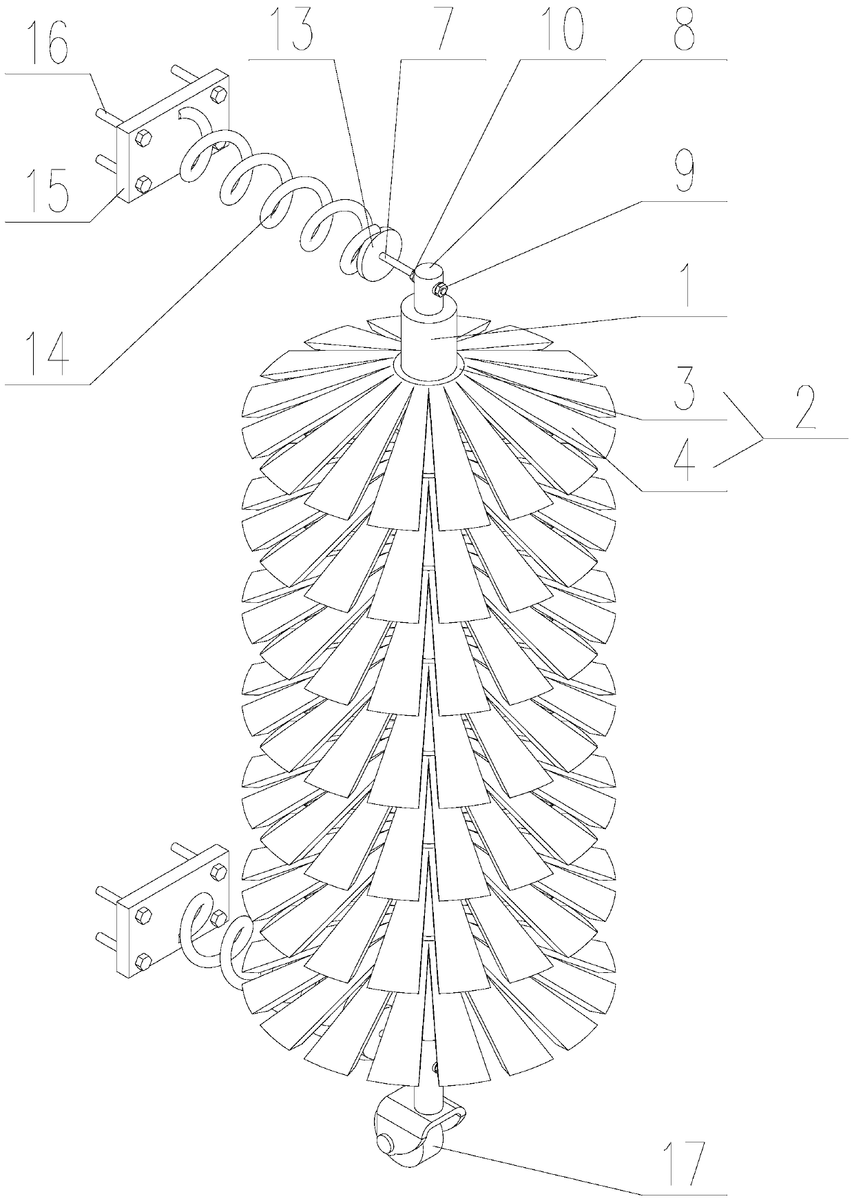
[0046] Such as Figure 3-Figure 14As shown, the car scratch protector for the corner surface of the underground garage of the present invention includes a support assembly and a rotating assembly, and the rotating assembly includes a rotating shaft 1 and a plurality of elastic contacts 2, the axis of the rotating shaft 1 is perpendicular to the ground, and the contact The parts 2 are arranged along the axis of the rotating shaft 1, and the contact parts 2 are all sleeved on the rotating shaft 1;
[0047] The support assembly is fixed on the wall, and there are two support assemblies, which are respectively located at the upper and lower ends of the rotating shaft 1. The upper and lower ends of the rotating shaft 1 are respectively connected to a supporting assembly in rotation, and the rotating shaft 1 can support the assembly relatively. Rotate around its own axis.
[0048] The contact piece 2 can be made of rubber and can elastically contract in any shape in the horizontal ...
Embodiment 2
[0053] This embodiment is a specific implementation description for the contact piece 2 .
[0054] Such as Figure 3-Figure 9 As shown, in the present invention, the contact member 2 includes an elastic connecting ring 3 and a plurality of rubber strips 4, the connecting ring 3 is a split ring, one end of the rubber strip 4 is connected to the outer wall of the connecting ring 3, and the rubber The strips 4 are evenly distributed at regular intervals along the outer circumference of the connecting ring 3;
[0055] The length of the circumference of the inner ring of the connecting ring 3 is consistent with the circumference of the cross-section of the rotating shaft 1 , and the inner ring of the connecting ring 3 is connected to the side wall of the rotating shaft 1 by Velcro.
[0056] The connecting ring 3 is a split ring, so that it can be quickly sleeved on the rotating shaft 1 through its own opening, or removed from the rotating shaft 1, which reduces the manufacturing d...
Embodiment 3
[0063] This embodiment is to illustrate the implementation structure of the support assembly.
[0064] Such as Figure 3-Figure 6 As shown, in the present invention, the support assembly includes a screw rod 7, a connecting block 8, a tightening nut 9, a positioning nut 10 and a bearing 11, and a mounting hole 12 is arranged on the connecting block 8, and the axis of the mounting hole 12 Coinciding with the axis of the rotating shaft 1, the inner and outer rings of the bearing 11 are interference fit with the rotating shaft 1 and the mounting hole 12 respectively;
[0065] One end of the screw rod 7 is threaded with the positioning nut 10, and its other end passes through the connecting block 8 and is threaded with the tightening nut 9, and the end faces of the tightening nut 9 and the positioning nut 10 are all in contact with the side wall of the connecting block 8, and the screw rod One end of 7 is connected with wall.
[0066] Tighten the nut 9 and the positioning nut 10...
PUM
 Abstract
Description
Claims
Application Information
 - R&D
- Intellectual Property
- Life Sciences
- Materials
- Tech Scout
- Unparalleled Data Quality
- Higher Quality Content
- 60% Fewer Hallucinations
Browse by: Latest US Patents, China's latest patents, Technical Efficacy Thesaurus, Application Domain, Technology Topic, Popular Technical Reports.
© 2025 PatSnap. All rights reserved.Legal|Privacy policy|Modern Slavery Act Transparency Statement|Sitemap|About US| Contact US: help@patsnap.com