
Construction method for water-rich sand layer shield to pass through steel tube soil nail area

A technology of water-rich sand layer and construction method, which is used in earth-moving drilling, infrastructure engineering, sheet pile wall, etc., can solve the problems of inability to excavate, wear of cutter head and cutter, and high construction cost, and achieve excellent long-term strength and durability. , The effect of reducing tool wear and saving construction costs

Active Publication Date: 2019-12-31
POWERCHINA RAILWAY CONSTR
View PDF8 Cites 8 Cited by
  • Summary
  • Abstract
  • Description
  • Claims
  • Application Information

AI Technical Summary

Problems solved by technology

[0006] In the prior art, there is an essential difference in material between the steel strands used in the anchor cables and the steel pipes used in the soil nails. The steel strands have high strength but flexibility, and the steel pipes have high strength and strong rigidity. The stranded wire can be wound on the drill bit of the rotary drilling rig and the cutterhead cutter, but the steel pipe cannot be wound on the drill bit of the rotary drilling rig and the cutterhead cutter. , and the wear of the cutterhead cutter during excavation is also very serious, which makes it difficult to construct the shield through the steel pipe soil nailing area, or even impossible to excavate, and the construction cost is high
[0007] Aiming at the problems of difficult construction and high construction cost of shield tunneling through the steel pipe soil nailing area in the prior art, no effective solution has been proposed so far

Method used


Image

  • Construction method for water-rich sand layer shield to pass through steel tube soil nail area
  • Construction method for water-rich sand layer shield to pass through steel tube soil nail area

Examples


Embodiment Construction

[0049] The present invention will be further described in detail below in conjunction with the accompanying drawings and specific embodiments.

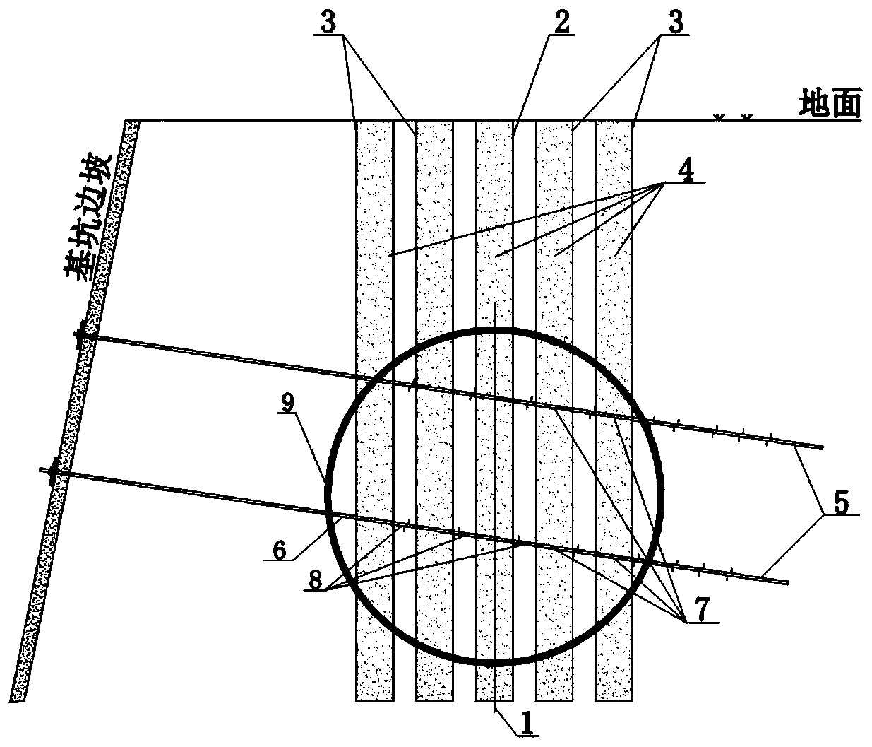
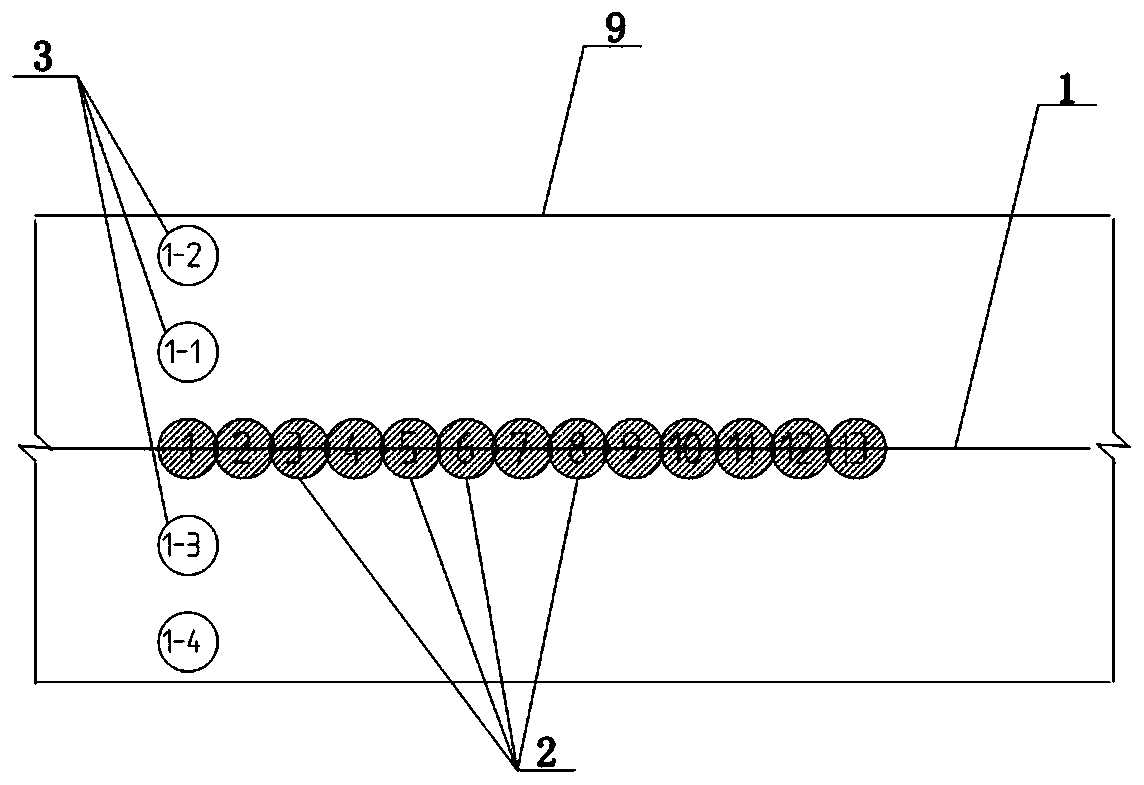
[0050] like figure 1 and figure 2 As shown, the method includes:

[0051] Step 1. Clean up the gravel and debris in the construction site, level the construction site, and compact and harden the construction site.

[0052] Step 2. Design the position of the longitudinal probe hole 2 along the tunnel centerline 1. The diameter of the longitudinal probe hole 2 is φ800mm, the hole distance is 750mm, and the occlusal width is 50mm. By analogy, the position of the horizontal clearance hole 3 is confirmed according to the position of the longitudinal probe hole 2. The diameter of the horizontal clearance hole 3 is φ800 mm, and the hole distance is 1300 mm. out), and add a sub-serial number on the basis of the number of the longitudinal probe hole 2 as the number of the horizontal clearance hole 3. 2#, 1-3#, 1-4#, and so on, are used to...


PUM


Abstract

The invention discloses a construction method for a water-rich sand layer shield to pass through a steel tube soil nail area. According to the method, a steel tube soil nail is cut and twisted off with the adoption of a high-power rotary digging drilling-jumping hole, the cutting-off sole pressing steel tube is directly pressed into a space below 500 mm of the bottom of a tunnel, the length of theretained steel tube left in the tunnel is not greater than 500 mm, the discharge requirement of the shield is met, the drilling engineering quantity of a transverse barrier clearing hole is reduced to the greatest extent, a drilling hole is backfilled by mortar, excavation parameters of the shield are controlled, and the shield excavates through the steel tube soil nail area; and the method is easy to operate, abrasion of a cutter head and a cutting tool due to the fact that the shield directly passes through the steel tube area is reduced, and the situation that major accidents of surface collapse, building damage and the like happen due to the fact that direct excavation of the shield results in winding of the steel tube soil nail on the cutter head of the shield and causes disturbanceof a soil body is avoided. The problem that a shield tunneling machine is difficulty in construction and high in construction cost when passing through a barrier area.

Description

technical field [0001] The invention relates to the technical field of urban rail transit construction, in particular to a construction method for a water-rich sand layer shield tunneling through a steel pipe soil nailing area. Background technique [0002] The construction operation of the soil nail wall support structure is simple and convenient, and the construction cost is low. It is widely used in the deep foundation pit enclosure structure. Subsequent engineering construction brought a series of troubles. When the Harbin Metro Line 2 shield machine passed through the 360 ​​Building in Jingwei Street, the line encountered a large number of steel pipes with a diameter of φ75mm and a wall thickness of 5.5mm in the range of 130m from the 440th ring to the 549th ring. The length of the nails ranges from 15 to 18m. There are threaded steel anchors with a welding length of 500mm and a diameter of φ22 on the steel pipe wall. There are two layers of 76 steel pipe soil nails int...

Claims


Application Information

Patent Timeline
IPC IPC(8): E21D9/00E21D9/06E21D11/10E02D5/76
CPCE02D5/76E21D9/001E21D9/0607E21D9/0685E21D11/105
Inventor 毛宇飞
Owner POWERCHINA RAILWAY CONSTR
Learn More