
Oil and gas multiphase-flow multi-cavity intelligent heat preservation pipeline structure and construction method

A heat preservation pipeline and multi-phase flow technology, applied in the field of pipelines, can solve the problems of poor heat preservation performance of the conveying medium, single conveying mode, and small pipe diameter, etc., and achieve the effects of improving seismic performance, good long-term airtightness, and high tensile strength

Active Publication Date: 2019-12-31
NORTHEAST GASOLINEEUM UNIV
View PDF5 Cites 0 Cited by
  • Summary
  • Abstract
  • Description
  • Claims
  • Application Information

AI Technical Summary

Problems solved by technology

[0003] The purpose of the present invention is to overcome the shortcomings of the above-mentioned prior art, and provide an oil-gas multi-phase flow multi-cavity intelligent heat preservation pipeline structure and construction method, which is used to solve the problem of small diameter, stability, impermeability, etc. of traditional pipelines. In order to solve the problems of poor performance, low transmission efficiency, single transportation mode, and poor thermal insulation performance of the transmission medium in high and severe cold regions, it also provides a construction method for this oil-gas multi-phase flow multi-cavity intelligent thermal insulation pipeline structure system

Method used


Image

  • Oil and gas multiphase-flow multi-cavity intelligent heat preservation pipeline structure and construction method
  • Oil and gas multiphase-flow multi-cavity intelligent heat preservation pipeline structure and construction method
  • Oil and gas multiphase-flow multi-cavity intelligent heat preservation pipeline structure and construction method

Examples


Embodiment 1

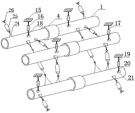
[0067] refer to figure 1 , this oil-gas multi-phase flow multi-cavity intelligent insulation pipeline structure is composed of three pipelines connected by GFRP anti-buckling energy-dissipating dampers, and the three pipelines are arranged on the three vertices of an equilateral triangle. Among them, a single pipeline is composed of straight pipeline monomers connected by integral nodes, combined with Figure 4 , Figure 5 As shown, the straight pipe unit is formed by two seamless inner and outer layers of wound GFRP circular pipes, annular heat transfer plates and interlayer self-compacting fine stone concrete, as shown in Fig. Figure 8 , Figure 9 , Figure 10 , Figure 11 As shown, the inner side of the outer GFRP tube is provided with GFRP shear connection keys according to a certain rule, and the outer side of the inner GFRP tube is provided with GFRP high-strength bolts according to a certain rule. Fixed, straight pipeline monomers are connected by integral nodes o...

Embodiment 2

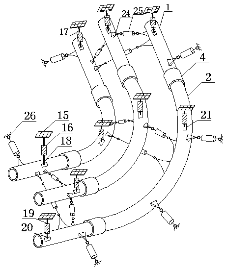
[0074] refer to figure 2 , this oil-gas multi-phase flow multi-cavity intelligent insulation pipeline structure is composed of three pipelines connected by GFRP anti-buckling energy-dissipating dampers, and the three pipelines are arranged on the three vertices of an equilateral triangle. Among them, a single pipeline is composed of straight pipeline monomers and curved pipeline monomers connected by integral nodes. Figure 12 As shown, the curved pipe unit is formed by two seamless inner and outer layers of wound GFRP circular pipes, annular heat transfer plates and interlayer self-compacting fine stone concrete, as shown in Fig. Figure 9 , Figure 11 As shown, the inner side of the outer GFRP tube is provided with GFRP shear connection keys according to a certain rule, and the outer side of the inner GFRP tube is provided with GFRP high-strength bolts according to a certain rule. Fixed, the integral node field connection is adopted between the straight pipe unit and the ...

Embodiment 3

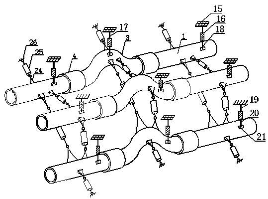
[0077] refer to image 3 , this oil-gas multi-phase flow multi-cavity intelligent insulation pipeline structure is composed of three pipelines connected by GFRP anti-buckling energy-dissipating dampers, and the three pipelines are arranged on the three vertices of an equilateral triangle. Among them, a single pipeline is composed of straight pipeline monomers and span pipeline monomers connected through integral nodes, combined Figure 13 As shown, the spanning pipe unit is formed by two seamless inner and outer layers of wound GFRP circular pipes and the self-compacting fine stone concrete sandwiched in the annular heat transfer plate, as shown in Figure 9 , Figure 11 As shown, the inner side of the outer GFRP tube is provided with GFRP shear connection keys according to a certain rule, and the outer side of the inner GFRP tube is provided with GFRP high-strength bolts according to a certain rule. Fixed, straight pipeline monomers and spanning pipeline monomers are connec...


PUM


Abstract

The invention discloses an oil and gas multiphase-flow multi-cavity intelligent heat preservation pipeline structure and a construction method, and relates to the technical field of pipelines. The structure is formed through sequential connection of three pipelines through a GFRP buckling-prevention energy dissipation damper, axes of the three pipelines are connected in sequence to form an equilateral triangle, each pipeline comprises a pipeline single body and a whole type joint, each pipeline single body comprises an outer layer GFRP round pipe, an inner layer GFRP round pipe, a self-compaction fine aggregate concrete layer and an annular heat transfer plate, an outer layer GFRP round pipe reserved bolt hole and a heat conduction pipe mounting hole are formed in the outer wall of each outer layer GFRP round pipe, the heat conduction pipe mounting holes are connected with temperature control devices through steel anchor racks, two pipeline single bodies are connected through the wholetype joints, and concrete pouring holes and exhaust holes are formed in the outer walls of the whole type joints. The oil and gas multiphase-flow multi-cavity intelligent heat preservation pipeline structure and the construction method solve the problems that a traditional pipeline is small in diameter, poor in stability and anti-permeability, low in conveying efficiency, single in conveying manner, and poor in heat preservation property of conveying media in the high and cold area.

Description

Technical field: [0001] The invention relates to the technical field of pipelines, in particular to an oil-gas multiphase flow multi-cavity intelligent heat preservation pipeline structure and a construction method. Background technique: [0002] Conventional long-distance pipelines are mostly round steel pipes and reinforced concrete round pipes, with diameters ranging from 0.5 meters to 1.5 meters. One end adopts the form of an enlarged head, and the connection between the pipes is realized through the head. The liquid is transported in the steel pipe all the year round, and it is easy to rust. Long-term erosion will reduce the effective thickness of the pipe wall, reduce the rigidity of the pipe wall, and local buckling will easily occur under the pressure of the soil and the outside world. At the same time, due to the erosion of the inner wall by the liquid in the pipeline, there are more and more impurities. It is difficult to meet the quality inspection standards, and ...

Claims


Application Information

Patent Timeline
IPC IPC(8): F16L9/14F16L9/19F16L13/11F16L55/033F16L59/14F16L59/20F16L53/30B28B21/56B28B21/72B28B21/82
CPCB28B21/56B28B21/72B28B21/82F16L9/14F16L9/19F16L13/11F16L55/033F16L59/14F16L59/182F16L59/20F16L53/30
Inventor 马令勇计静张云峰姜良芹王莉莉梁媛
Owner NORTHEAST GASOLINEEUM UNIV
Learn More